Measurement device and printing apparatus

a measurement device and printing apparatus technology, applied in the direction of optical radiation measurement, instruments, spectrometry/spectrophotometry/monochromators, etc., can solve the problems of increasing complexity of configuration, difficulty in high-precision colorimetry, and increasing the number of components, so as to achieve high-precision measurement

Active Publication Date: 2018-06-26
SEIKO EPSON CORP
View PDF1 Cites 0 Cited by
  • Summary
  • Abstract
  • Description
  • Claims
  • Application Information

AI Technical Summary

Benefits of technology

[0009]An advantage of some aspects of the invention is to provide a measurement device and a printing apparatus capable of high precision measurement.
[0014]In the application example, the illumination direction and the measurement direction are different. For example, in a case where the illumination light is radiated from the normal direction of the measurement object, and the measurement light reflected in the normal direction is measured with the measurement unit, the specular reflection component is included in the measurement light, and the measurement precision is lowered, particularly in a case of performing colorimetry or the like. In contrast, because the illumination direction and the measurement direction are different in the application example, the specular reflection component included in the measurement light is reduced, and improvements in the measurement precision are achieved.
[0020]Meanwhile, if the shape of the measurement region is made an ellipse in which the relative movement direction of the illumination region with respect to the measurement region when the position of the measurement object is made the long axis, the illumination region can be included in the measurement region, even in a case where fluctuations in the measurement object arise. Since the area of the region can be reduced compared to a case where the measurement region is circular, the influence of stray light can be suppressed, and further improvements in the measurement precision are achieved.
[0022]In the application example, the shape of the measurement region due to the concave mirror provided in the measurement unit is made an ellipse. In this case, the elliptical measurement region can be given a simple structure.
[0023]That is, in a configuration in which only light from the elliptical measurement region passes through the measurement unit using a plurality of slits or the like, the measurement light of the elliptical measurement region is incident in the measurement unit as parallel light. In this case, since the shape of the optical path orthogonal to the main light beam of the measurement light is made the same shape and same size as the measurement region, it is necessary to also use a light receiving unit with the same size. Although a configuration can be used in which the measurement light is collected on the light receiving unit by a lens or the like, the number of components increases when a lens is disposed in addition to the slits, and the configuration increases in complexity. In contrast thereto, in the application example, the measurement region can be made an ellipse with a single concave mirror, and light from the measurement region can be collected with respect to the light receiving unit by the concave mirror. Thus, the configuration can be further simplified, and size reductions in the measurement device can be promoted.

Problems solved by technology

In this way, when the illumination region or the measurement region move, because the light quantity of illumination light fluctuates in the portion where the measurement region and the illumination region are superimposed, a problem arises where the light quantity of the measurement light incident on the measuring device also fluctuates and it is difficult to carry out colorimetry with high precision.
Although a configuration can be used in which the measurement light is collected on the light receiving unit by a lens or the like, the number of components increases when a lens is disposed in addition to the slits, and the configuration increases in complexity.

Method used


Image

  • Measurement device and printing apparatus
  • Measurement device and printing apparatus
  • Measurement device and printing apparatus

Examples


first embodiment

[0064]Below, the first embodiment according to the invention will be described based on the drawings. In the embodiment, a printer 10 (ink jet printer) provided with the measurement device will be described below as an example of the printing apparatus of the invention.

Schematic Configuration of Printer

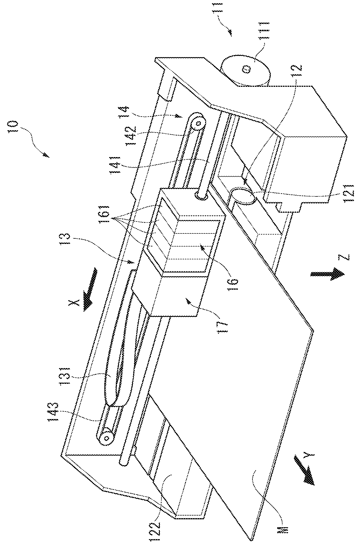
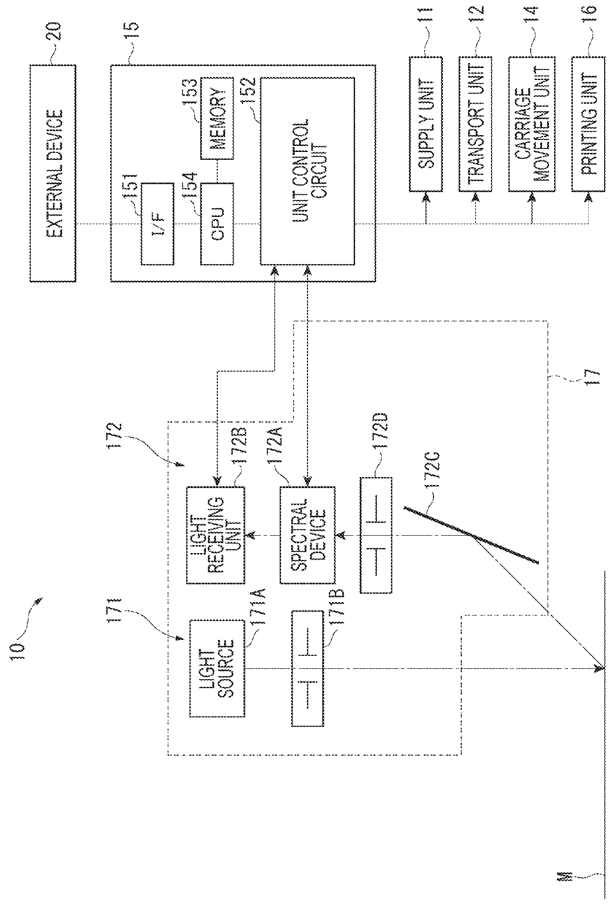
[0065]FIG. 1 is a drawing illustrating a schematic configuration of the external appearance of the printer 10 of the first embodiment. FIG. 2 is a block diagram illustrating a schematic configuration of the printer 10 of the embodiment.

[0066]As illustrated in FIG. 1, the printer 10 is provided with a supply unit 11, a transport unit 12, a carriage 13, a carriage movement unit 14, and a control unit 15 (refer to FIG. 2). The printer 10 controls each unit 11, and 14, and the carriage 13 and prints an image on a medium M (measurement object of the invention) based on printing data input from an external device 20, such as a personal computer. The printer 10 of the embodiment forms a colo...

second embodiment

[0149]Next, the second embodiment according to the invention will be described.

[0150]In the above-described first embodiment, a configuration in which the illumination region RL and the measurement region RD are circular was described as an example. In contrast, the second embodiment differs from the first embodiment on the feature of the measurement region RD being elliptical.

[0151]FIG. 10 is a drawing illustrating the schematic configuration of the second embodiment according to the invention. It should be noted that in the following description, matters already described are given the same reference numerals and description thereof will be omitted or simplified.

[0152]As illustrated in FIG. 10, the printer 10A of the second embodiment is provided with a supply unit 11, a transport unit 12, a carriage 13, a carriage movement unit 14, and a control unit 15, similarly to the first embodiment. The carriage 13 includes a printing unit 16 and a spectrometer 17A similarly to the first em...

modification example of second embodiment

[0163]In the example illustrated in FIG. 11, although an example is given in which the end portions on the −X side of the measurement region RD and the illumination region RL contact one another when the medium M is positioned at the first position P1 and the end portions on the −X side of the measurement region RD and the illumination region RL contact one another when the medium M is positioned at the second position P2, the measurement region RD may be as illustrated in FIG. 12.

[0164]FIG. 12 is a drawing illustrating the positional relationship of the measurement region RD and the illumination region RL when the medium M is viewed from the normal direction in the modification example of the second embodiment.

[0165]In the example illustrated in FIG. 12, the measurement region RD (RD1) contacts two points on the −X side of the circular illumination region RL when the medium M is positioned at the first position P1, and the measurement region RD (RD2) contacts two points on the +X s...


PUM

PropertyMeasurementUnit
angle of incidenceaaaaaaaaaa

Abstract

A spectrometer includes a light source that radiates illumination light, and a measurement unit that measures measurement light in which illumination light is reflected by a medium. In a case where an illumination region that is a region in which the medium is irradiated with illumination light is smaller than a measurement region that is a region of the medium measurable by the measurement unit and in which the movement of the medium in the direction is within a range of an acceptable fluctuation amount, the illumination region is included in the measurement region.

Description

BACKGROUND[0001]1. Technical Field[0002]The present invention relates to a measurement device, a printing apparatus, and the like.[0003]2. Related Art[0004]In image forming apparatuses, such as a printer, in the related art, a device provided with a colorimetry device that measures the color of a measurement object is known (for example, JP-A-2005-59552).[0005]The device disclosed in JP-A-2005-59552 is provided with a light source that radiates an illumination light on the measurement object, and measures the light reflected by the light source with a measuring device. The device disclosed in JP-A-2005-59552 includes a focal position of the illumination light that is set behind (opposite side to the measuring device) of the measurement object. In this case, the fluctuation amount in the light intensity of light received by the measuring device can be reduced and lowering of the measurement precision can be suppressed, even in a case where swelling (cockling) or the like arises due t...

Claims


Application Information

Patent Timeline
Patent Type & Authority Patents(United States)
IPC IPC(8): B41J29/38G01N21/25G01N21/27B41J11/00G01J3/46G01N21/31
CPCG01N21/251B41J11/0095B41J29/38G01J3/46G01N21/27G01N2201/0633G01N21/31G01N2201/062G01N2201/068G01N2201/0612G01J3/0289G01J3/26G01J3/50
Inventor GOMI, TSUGIO
Owner SEIKO EPSON CORP
Why Eureka
Try Eureka