Clamping bolt with integrated RFID transponder

a technology of rfid transponder and clamping bolt, which is applied in the direction of metal-working machine components, instruments, manufacturing tools, etc., can solve the problems of increased effort when mounting the clamping bolt, the inability to integrate the rfid transponder into the base body of the clamping bolt, and the inability to identify the clamping bolt independently of the position. , to achieve the effect of increasing the mechanical resilience of the connection and ensuring the connection

Active Publication Date: 2018-06-26
BALLUFF +1
View PDF12 Cites 0 Cited by
  • Summary
  • Abstract
  • Description
  • Claims
  • Application Information

AI Technical Summary

Benefits of technology

[0009]In principle, a conventional RFID transponder can be arranged in the attachment according to the invention. The RFID transponder preferably has an antenna that is arranged in the receptacle region around the through opening. If the through opening has a circular cross-section, the antenna can be arranged around the through opening in the receptacle region, for example, multiple times and in a circular manner. In this way, the attachment according to the invention can receive a long RFID antenna that enables data to be readout across greater distances.
[0011]The circuit board is arranged in the receptacle region substantially in parallel to the through opening. It thus stands upright in the receptacle region. As a result, it occupies the space of the receptacle region substantially only in parallel to the longitudinal axis of the through opening, but not orthogonally thereto. As a result, the diameter of the attachment can be adapted to the dimensions of a clamping bolt without thus having to consider the construction space requirements of the RFID transponder.
[0014]The receptacle region is preferably filled with a filling material. This filling material is, in particular, electrically non-conductive, such that it does not exert a shielding effect on the antenna of the RFID transponder. The filling material prevents an unwanted position change of the RFID transponder in the receptacle region. In addition, it protects the RFID transponder from mechanical damage. Particularly suitable filling materials are thermoplastic plastics by means of which the receptacle region can be cast. These are selected, in particular, from the group of polyurethane casting resins.
[0015]It is particularly preferred that the filling material is arranged in the receptacle region in such a way that it forms a common plane with the contact surface. In this way, the filling material increases the contact surface and enables a particularly secure and fixed connection of the attachment to a clamping bolt by this being fastened to the attachment both via the contact surface of the base body and via the filling material.
[0016]Furthermore, it is preferred that the base body has recesses that extend through the contact surface. These enable an engagement with engaging elements of the clamping bolt provided for this. This increases the mechanical resilience of a connection between the attachment and the clamping bolt.
[0018]The clamping bolt according to the invention has a circular-cylindrically shaped clamping region in the conventional manner. A first boundary region and a second boundary region border the clamping region along the longitudinal axis of the clamping bolt. To do so, each boundary region has a greater external diameter than the clamping region. A through opening runs along a longitudinal axis of the clamping bolt, said through opening being able to receive a screw for connecting the clamping bolt to a carrier component. The attachment according to the invention is arranged on the first boundary region. Together with the attachment, the clamping bolt according to the invention completes all tasks of a conventional clamping bolt. Thus, the RFID transponder enables the identification of the clamping bolt in the attachment independent of the location.

Problems solved by technology

When using clamping systems, the problem arises that a clamping bolt cannot be identified independently of the position without changing the function of the clamping bolt.
An integration of a RFID transponder into the base body of a clamping bolt is not possible since this usually consists of an electrically conductive metal and thus would shield the radio waves.
Thus, an increased effort when mounting the clamping bolt would emerge.

Method used


Image

  • Clamping bolt with integrated RFID transponder
  • Clamping bolt with integrated RFID transponder
  • Clamping bolt with integrated RFID transponder

Examples


Embodiment Construction

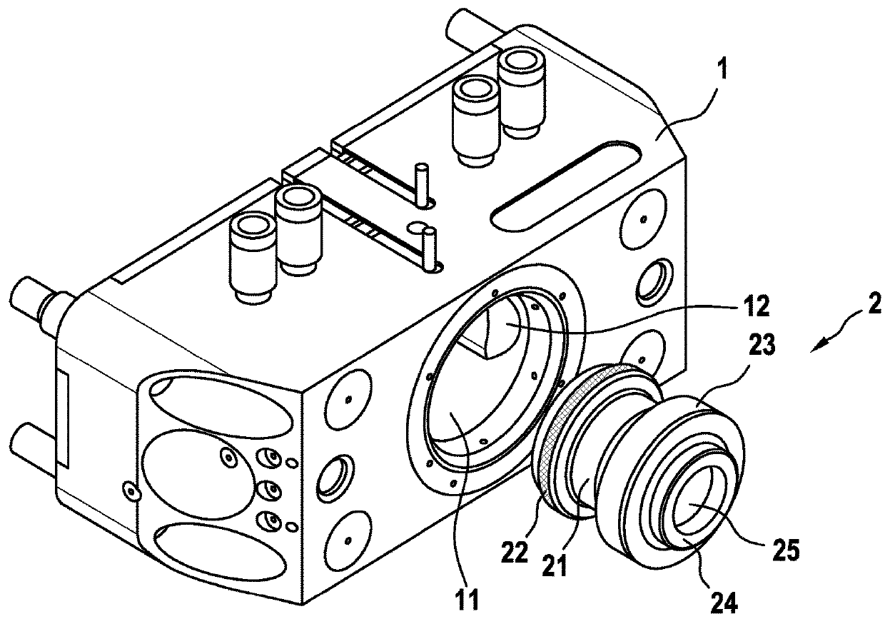
[0031]A conventional zero-point clamping system, as is known from DE 10 2013 201 994 A1, is depicted in FIG. 1. It has a clamping receiver 1, a circular-cylindrically shaped insertion opening 11 being found in the base housing thereof. Locking elements 12 are provided in the clamping receiver 1, said locking elements 12 being formed as sliders. They are able to be shifted from a radially external unlocking position into a radially internal locking position. When shifting the locking elements 12 into the radially internal locking position, a clamping bolt 2 inserted into the insertion opening 11 is firstly retracted into the insertion opening 11 and then locked in place there.

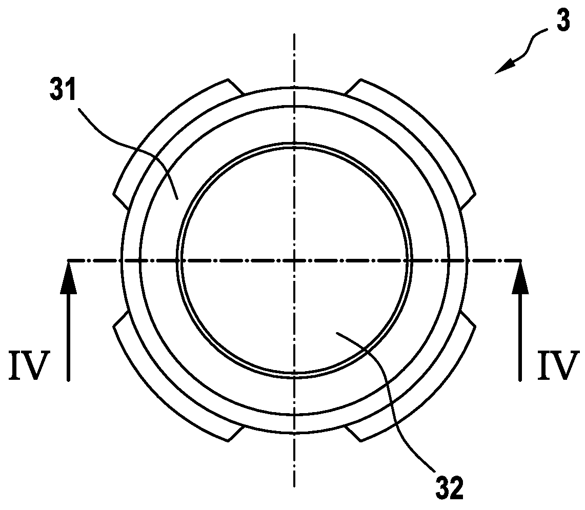
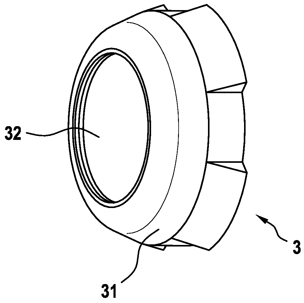
[0032]The clamping bolt 2 has a circular-cylindrically shaped clamping region 21. This is bordered by a conical first boundary region 22 and a conical second boundary region 23. When the clamping bolt 2 is inserted into the insertion opening 11 and the locking elements 12 are in their locking position, then the ...


PUM


Abstract

An attachment for a clamping bolt has a base body and an opening which passes through the base body. Around the through-going opening runs a contact face which is positioned orthogonally on the longitudinal axis of the through-going opening and which is configured to make contact with the clamping bolt. A receptacle region runs around the through-going opening in the basic body, between the through-going opening and the contact face. An RFID transponder is arranged in the receptacle region. The clamping bolt has a circular-cylinder-shaped clamping region. A first boundary region and a second boundary region bound the clamping region along the longitudinal axis of the clamping bolt Each boundary region has a larger external diameter than the clamping region. The attachment is arranged on the first boundary region. A through-going opening runs along the longitudinal axis of the clamping bolt.

Description

CROSS REFERENCE TO RELATED APPLICATIONS[0001]This application is the National Stage of PCT / DE2015 / 100024 filed on Jan. 19, 2015, the disclosure of which is incorporated by reference. The international application under PCT article 21(2) was not published in English.[0002]The present invention relates to an attachment for a clamping bolt. A RFID transponder is arranged in the attachment. Furthermore, the present invention relates to a clamping bolt that has the attachment according to the invention.PRIOR ART[0003]Zero-point clamping systems are provided to fix carrier components, in particular workpiece carriers or clamping plates, exactly in a predetermined position with repeat accuracy. They are used, for example, when processing cylinder heads and crank housings. The zero-point clamping modules to be used thus generally provide a receiver in which a clamping bolt can be inserted. Furthermore, clamping means are provided which act against the clamping bolt in a radially internal po...

Claims


Application Information

Patent Timeline
Patent Type & Authority Patents(United States)
IPC IPC(8): G06K19/06B23Q1/00G06K19/077G06K19/07
CPCG06K19/07758G06K19/07773G06K19/0723B23Q1/0072
Inventor BEUTLER, ROBERTUHLE, ALEXANDER
Owner BALLUFF
Why Eureka
Try Eureka