High-side power switch control circuit

a control circuit and power switch technology, applied in electronic switching, pulse automatic control, pulse technique, etc., can solve the problems of burnt or damaged power switches, integrated circuits b>100/b> can be burned or damaged, etc., and achieve the effect of flexibl

Active Publication Date: 2019-09-24
MOSWAY TECH LTD
View PDF6 Cites 0 Cited by
  • Summary
  • Abstract
  • Description
  • Claims
  • Application Information

AI Technical Summary

Benefits of technology

[0007]In accordance with a first aspect of the invention, there is provided a circuit for controlling a high-side power switch, comprising: a level shifting circuit configured to receive an input signal for selectively configuring a logic command circuit to be in a set state for providing a first output signal to the high-side power switch and in a reset state for providing a second output signal different from the first output signal to the high-side power switch; and a regulation circuit configured to detect a signal indicative of the output signal provided to the high-side power switch and to change a sensitivity of the level shifting circuit to the input signal based on the detected signal. By changing the sensitivity of the level shifting circuit to the input signal based on the detected signal, the change of state of the level shifting circuit can be flexibly and reliably controlled. In one embodiment, the input signal comprises a signal pulse received from a pulse generator. The input signal may contain noise.
[0008]In one embodiment of the first aspect, the regulation circuit is configured to arrange the level shifting circuit to be in a set-dominant configuration in which a sensitivity of the level shifting circuit to an input signal for configuring the logic command circuit to a reset state is reduced in a period during which the detected signal indicates a transition from the second output signal to the first output signal. By reducing the sensitivity in this manner, the level shifting circuit is less susceptible to unwanted change to the reset state caused by noise. Preferably, the sensitivity is reduced only during the period.
[0009]In one embodiment of the first aspect, the regulation circuit is configured to arrange the level shifting circuit to be in a set-dominant configuration in which a sensitivity of the level shifting circuit to an input signal for configuring the logic command circuit to a reset state is reduced when the detected signal indicates that the first output signal is provided to the high-side power switch. By reducing the sensitivity in this manner, the level shifting circuit is less susceptible to unwanted change to the reset state caused by noise.

Problems solved by technology

In some applications, such latch on / latch off fault can burn or damage the power switches in the external half bridge device (not shown) driven by the driver circuit.
In some other applications, even the integrated circuit 100 can be burnt or damaged.

Method used


Image

  • High-side power switch control circuit
  • High-side power switch control circuit
  • High-side power switch control circuit

Examples


Embodiment Construction

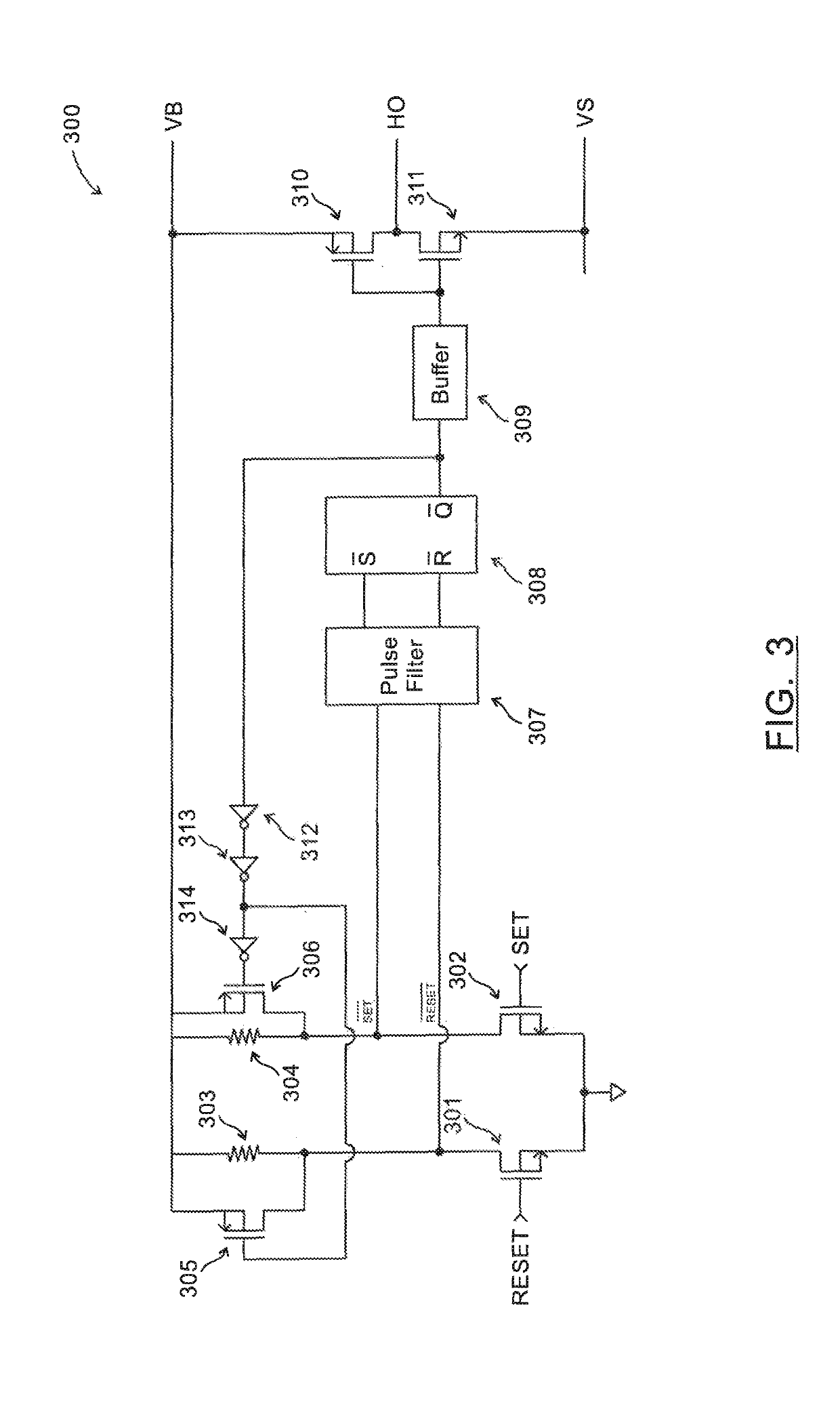
[0047]FIG. 3 shows a high-side control circuit 300 in one embodiment of the invention. The circuit 300 can be arranged to replace the conventional high-side control circuit (the high-side circuit portion downstream of the pulse generator) in the circuit 100 of FIG. 1. As shown in FIG. 3, the circuit 300 includes a level shifting circuit having two high voltage LDMOS devices 301, 302 each arranged to receive, at the gate terminal, a control signal from a pulse generator (not shown). In this embodiment, the pair of high voltage LDMOS devices 301 and 302 have the same device size. The high voltage LDMOS device 301 is connected with a resistor 303; the high voltage LDMOS device 302 is connected with a resistor 304. The other connecting terminals of both resistors 303, 304 are connected to VB. A RESET node is arranged between the device 301 and the resistor 303; a SET node is arranged between the device 302 and the resistor 304. The level shifting circuit is arranged to selectively confi...


PUM


Abstract

A circuit for controlling a high-side power switch includes a level shifting circuit configured to receive an input signal for selectively configuring a logic command circuit to be in a set state, for providing a first output signal to the high-side power switch, and in a reset state, for providing a second output signal, different from the first output signal, to the high-side power switch. The circuit also includes a regulation circuit configured to detect an indicative signal indicative of the output signal provided to the high-side power switch and to change sensitivity of the level shifting circuit to the input signal, based on the indicative signal that is detected.

Description

TECHNICAL FIELD[0001]The invention relates to a high-side power switch control circuit. More particularly, although not exclusively, the invention relates to a state dependent set-dominant level shifting circuit, a state dependent reset-dominant level shifting circuit, a state dependent set- and reset-dominant level shifting circuit for use in the high-side circuit of a bridge driver or a half-bridge driver.BACKGROUND[0002]FIG. 1 shows a conventional half-bridge driver circuit 100. The circuit 100 is arranged to receive a high-side input HIN and a low-side input LIN, for controlling a high-side output HO and a low-side output LO. The low-side output LO can change between voltage levels COM and VCC. For example, the potential of COM may be at ground (zero V) and the potential of VCC may be 20V. The high-side output HO can change between the floating voltage levels VS and VB. |VB−VS| is the magnitude of the power supply voltage for the high side circuit while |VCC−COM| is the magnitud...

Claims


Application Information

Patent Timeline
Patent Type & Authority Patents(United States)
IPC IPC(8): H03L5/00H03K17/687H03K19/0185
CPCH03K19/018507H03K17/6871
Inventor CHAN, ON BON PETER
Owner MOSWAY TECH LTD
Why Eureka
Try Eureka