Hydraulic drive apparatus

a hydraulic drive and apparatus technology, applied in the direction of mechanical devices, fluid couplings, couplings, etc., can solve the problems of limiting the speed upper limit of the vehicle to which the hydraulic drive apparatus is applied, and it is difficult to obtain stable running performance. , to achieve the effect of flexibl

Active Publication Date: 2010-04-15
KOMATSU LTD
View PDF8 Cites 18 Cited by
  • Summary
  • Abstract
  • Description
  • Claims
  • Application Information

AI Technical Summary

Benefits of technology

[0020]According to the present invention, the hydraulic drive apparatus includes the control unit which sets the maximum capacity limit value of the hydraulic motor in accordance with the upper limit of the output torque required for the hydraulic motor, and which sets the maximum capacity limit value of the hydraulic pump in accordance with the upper limit of the output torque. Therefore, even when the upper limit of the rotation number of the hydraulic motor is limited by setting the maximum capacity limit value of the hydraulic motor, it is possible to set the upper limit of the rotation number required for the hydraulic motor by setting the maximum capacity limit value of the hydraulic pump, and it is possible to flexibly set the apparatus in accordance with the desire of the operator.

Problems solved by technology

In such a condition, the high output torque at the time of start of the vehicle promotes slip, and there is a possibility that it becomes difficult to obtain stable running performance.
According to the above-described hydraulic drive apparatus, if the minimum tilting angle of the hydraulic motor is changed, it is possible to set the upper limit for the rotation number of the hydraulic motor, and the speed upper limit of the vehicle to which the hydraulic drive apparatus is applied can be limited.

Method used


Image

  • Hydraulic drive apparatus
  • Hydraulic drive apparatus
  • Hydraulic drive apparatus

Examples


Embodiment Construction

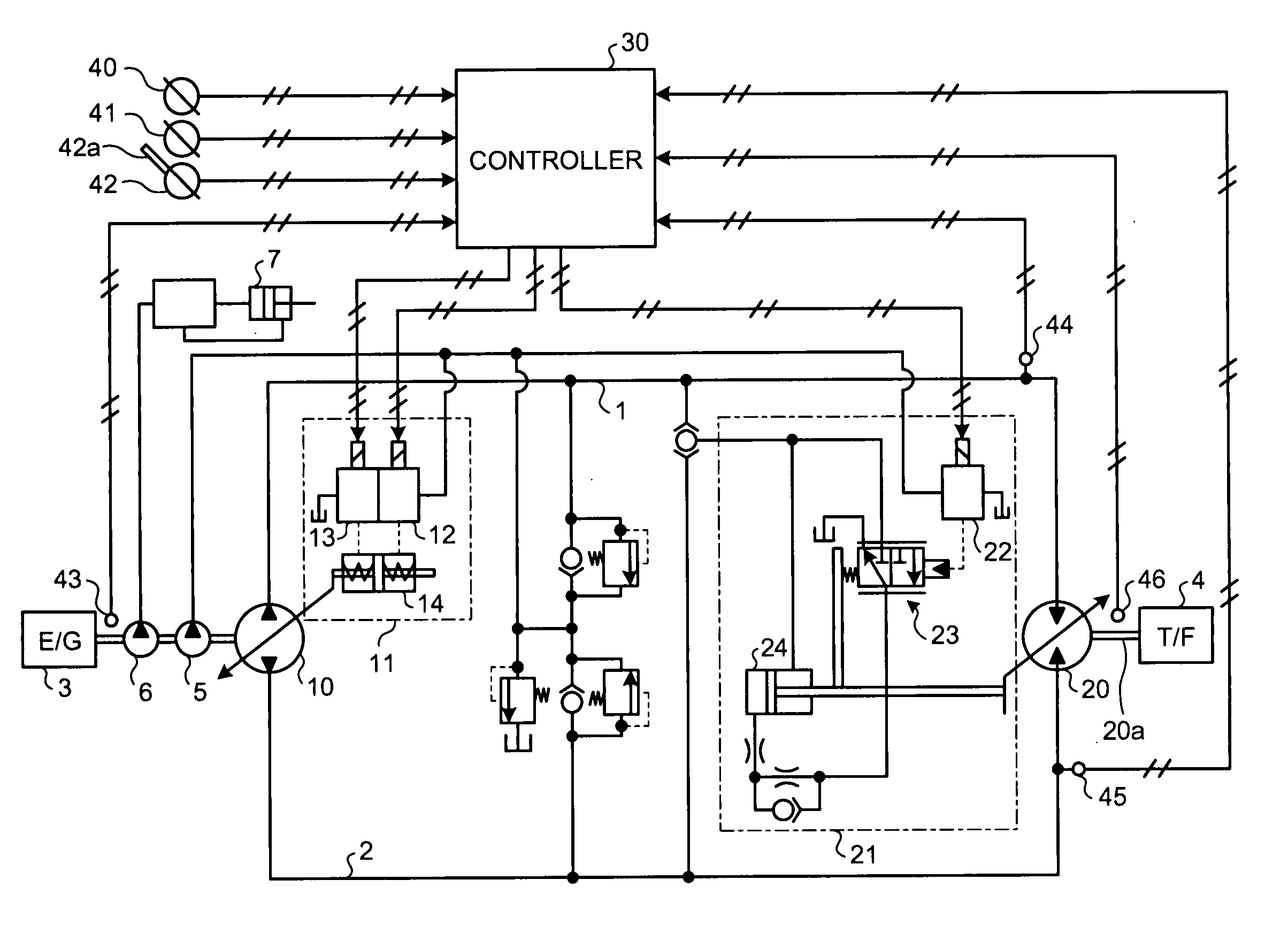
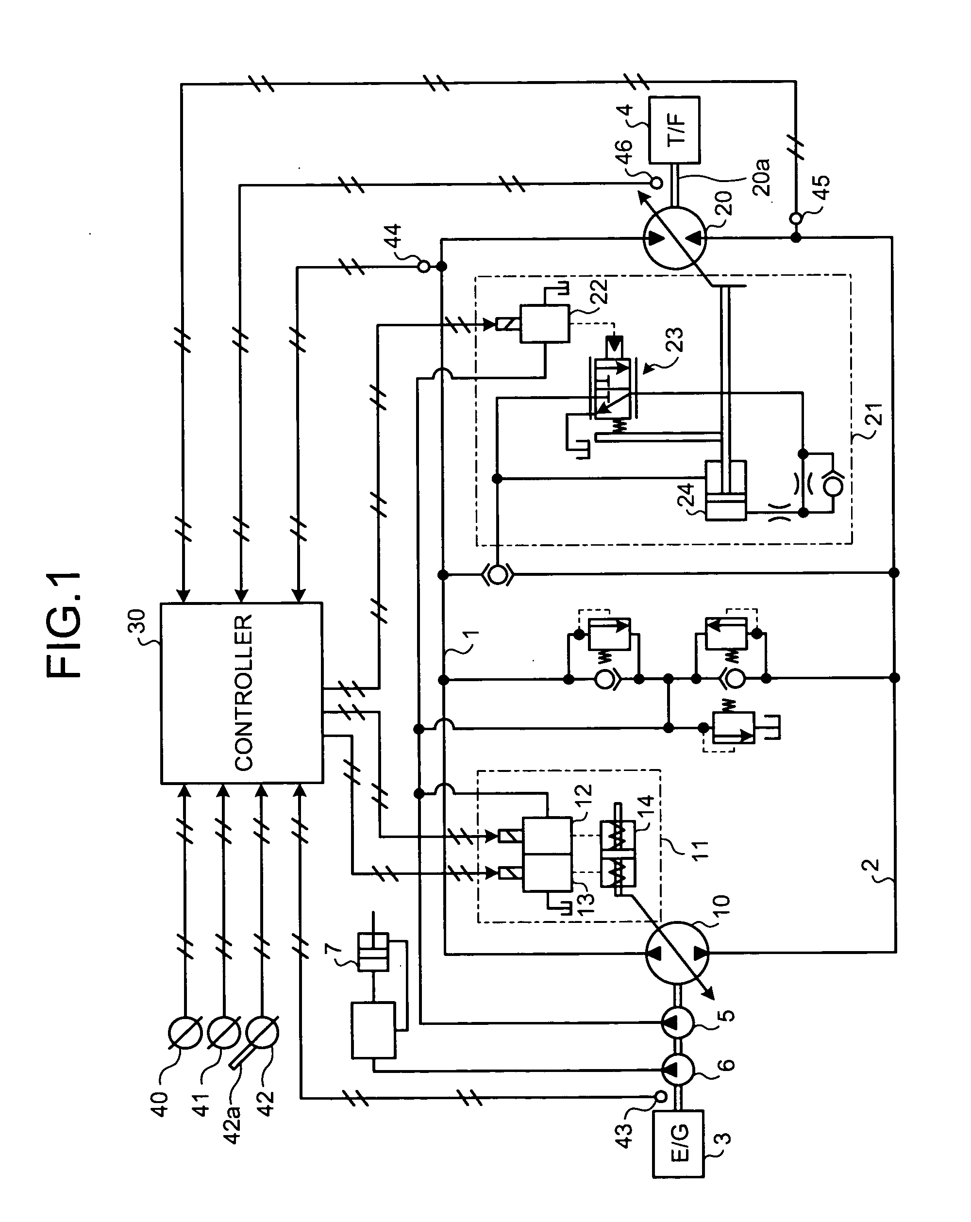
[0062]A preferred embodiment of a hydraulic drive apparatus according to the present invention will be explained in detail with reference to the accompanying drawings. FIG. 1 shows the hydraulic drive apparatus of the embodiment of the invention. The hydraulic drive apparatus shown here as an example is so-called HST, and is provided in a vehicle used as construction machine such as a wheel loader and a bulldozer. The hydraulic drive apparatus includes a hydraulic pump 10 and a hydraulic motor 20 connected to each other through oil pressure supply tubes 1 and 2 which is a closed circuit.

[0063]The hydraulic pump (“HST pump 10”, hereinafter) is driven by an engine 3 of a vehicle. In this embodiment, a variable displacement HST pump 10 capable of changing its capacity by changing a tilting angle of a swash plate is applied.

[0064]The hydraulic motor (“HST motor 20”, hereinafter) is driven by pressure oil discharged from the HST pump 10. In this embodiment, a variable displacement HST mo...


PUM


Abstract

The present invention provides a hydraulic drive apparatus which can flexibly be set. The hydraulic drive apparatus which drives a variable displacement hydraulic motor 20 by a pressure oil discharged from a variable displacement hydraulic pump 10 and outputs a driving force of the hydraulic motor 20 to outside. The hydraulic drive apparatus includes torque upper limit setting unit which sets an upper limit of an output torque with respect to the hydraulic motor 20, and control unit which sets a maximum capacity limit value of the hydraulic motor 20 in accordance with the upper limit of the output torque when the upper limit of the output torque is set by the torque upper limit setting unit, and which sets a maximum capacity limit value of the hydraulic pump 10 in accordance with the upper limit of the output torque.

Description

TECHNICAL FIELD[0001]The present invention relates to a hydraulic drive apparatus which drives a variable displacement hydraulic motor by pressure oil discharged from a variable displacement hydraulic pump and which outputs a driving force of the hydraulic motor to outside.BACKGROUND ART[0002]Some vehicles used as a construction machine such as a wheel loader and a bulldozer are provided with hydraulic drive apparatuses called HST (Hydro-Static Transmission) between driving wheels and engines which are driving sources. The hydraulic drive apparatus includes a variable displacement hydraulic pump driven by the engine, and a variable displacement hydraulic motor which is driven by pressure oil discharged from the hydraulic pump. A driving force of the hydraulic motor is transmitted to a driving wheel to run the vehicle.[0003]According to a vehicle to which the hydraulic drive apparatus is applied, by appropriately adjusting a capacity of the hydraulic pump and a capacity of the hydrau...

Claims


Application Information

Patent Timeline
Patent Type & Authority Applications(United States)
IPC IPC(8): F16H61/42F16H59/14F16H59/40F16H59/68F16H61/421F16H61/431F16H61/438
CPCB60W30/18172B60W2710/1038B60W2710/105F16H2059/6861F16H61/431F16H61/47F16H61/472F16H61/421F16H59/14F16H59/40F16H59/68F16H61/42
Inventor OHTSUKASA, NARITOSHI
Owner KOMATSU LTD
Why Eureka
Try Eureka