Automatic remote monitoring and diagnosis system

a remote monitoring and diagnosis system technology, applied in the direction of testing/monitoring control systems, process and machine control, instruments, etc., can solve the problems of sporadic measurement of data, trouble and abnormalities, and inability to monitor and diagnose abnormalities continuously

Active Publication Date: 2013-07-18
TOSHIBA MITSUBISHI-ELECTRIC IND SYST CORP
View PDF6 Cites 21 Cited by
  • Summary
  • Abstract
  • Description
  • Claims
  • Application Information

AI Technical Summary

Benefits of technology

[0014]In the automatic remote monitoring and diagnosis system of the present invention, automatic measurement and automatic collection of environmental data and physical data related to electronic control devices and the like are continuously performed, the existence or nonexistence of an abnormality in the electronic control devices and the like is diagnosed by analyzing the collected data in real time, the automatic remote monitoring and diagnosis system has an effect that it is possible to automatically present results of the analysis and diagnosis and, as required, a remedy, and to be flexibly built according to the situation, state and the like of an object of monitoring, a diagnosis requester and the like.

Problems solved by technology

For example, electronic control devices for plant equipment or equipment of plants and the like (hereinafter referred to as “electronic control devices and the like”) are affected by the installation environment during the use thereof and troubles and abnormalities may sometimes occur.
That is, the measurement of data is sporadic, and the monitoring and diagnosis of abnormalities are not continuously performed for a long period of time.
Therefore, the investigation of the installation environment has the problem that the measurement, collection, analysis and reporting of data require much labor and expense.
However, the preparation of a report based on an analysis of data and results of the analysis are not automatically performed.
For this reason, it is necessary for the workers to retrieve the collected data, to perform the analysis and the preparation of a report, and these works require much labor and expense in the same manner as described above.

Method used


Image

  • Automatic remote monitoring and diagnosis system
  • Automatic remote monitoring and diagnosis system
  • Automatic remote monitoring and diagnosis system

Examples


embodiment 1

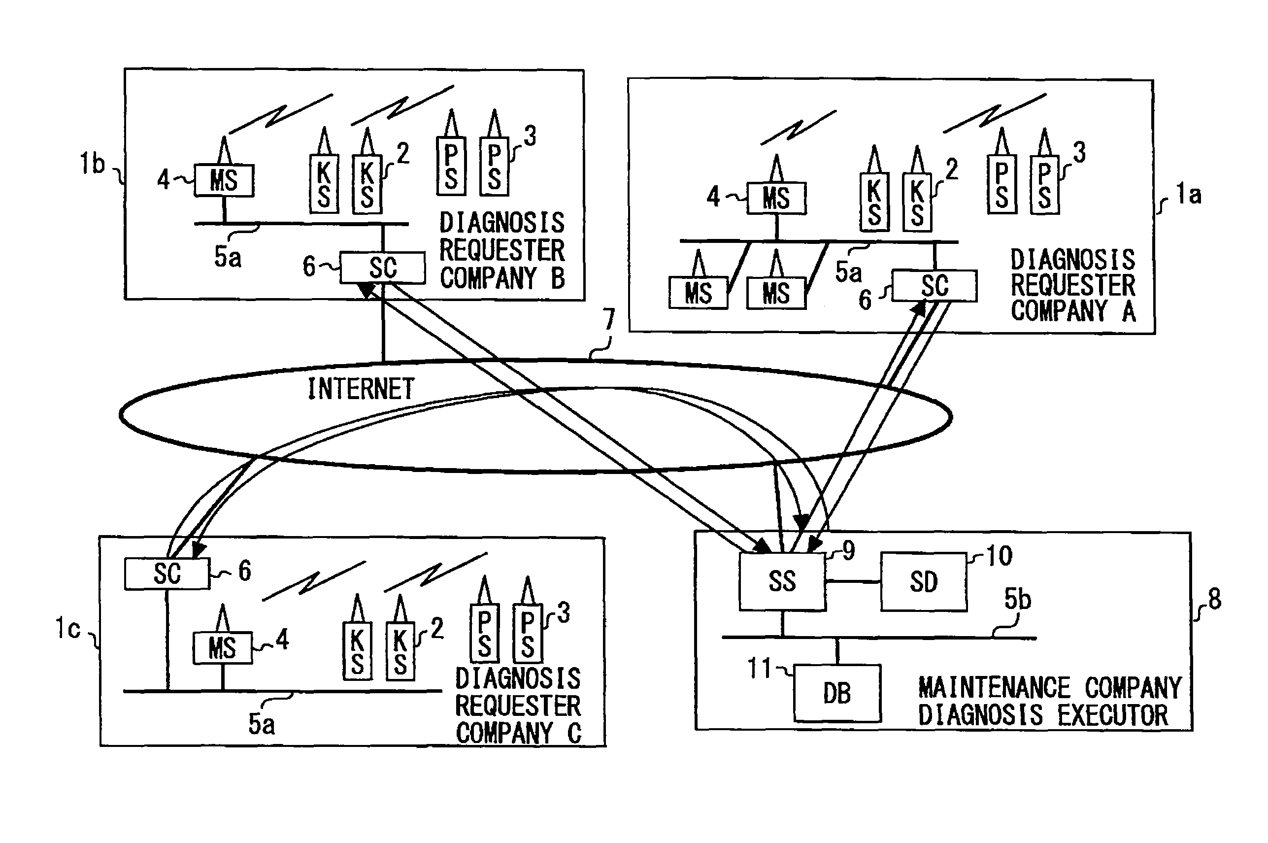
[0021]FIG. 1 is related to Embodiment 1 of the present invention. FIG. 1 shows the general configuration of an automatic remote monitoring and diagnosis system. In FIG. 1, reference numerals 1a, 1b, and 1c denote Company A, Company B, and Company C, respectively, which are diagnosis requesters for the state of electronic control devices and the like. Although in this case the number of diagnosis requesters is 3, any number is allowed. Company A 1a, Company B 1b, and Company C 1c are provided with electronic control devices and the like (not shown) which are the objects of monitoring and diagnosis of the automatic remote monitoring and diagnosis system of the present application invention. And environmental sensors 2 and physical sensors 3 are installed within cabinets of the electronic control devices and the like of these diagnosis requesters and in the vicinity of the electronic control devices and the like.

[0022]The environmental sensors 2 are sensor groups each consisting of a p...

embodiment 2

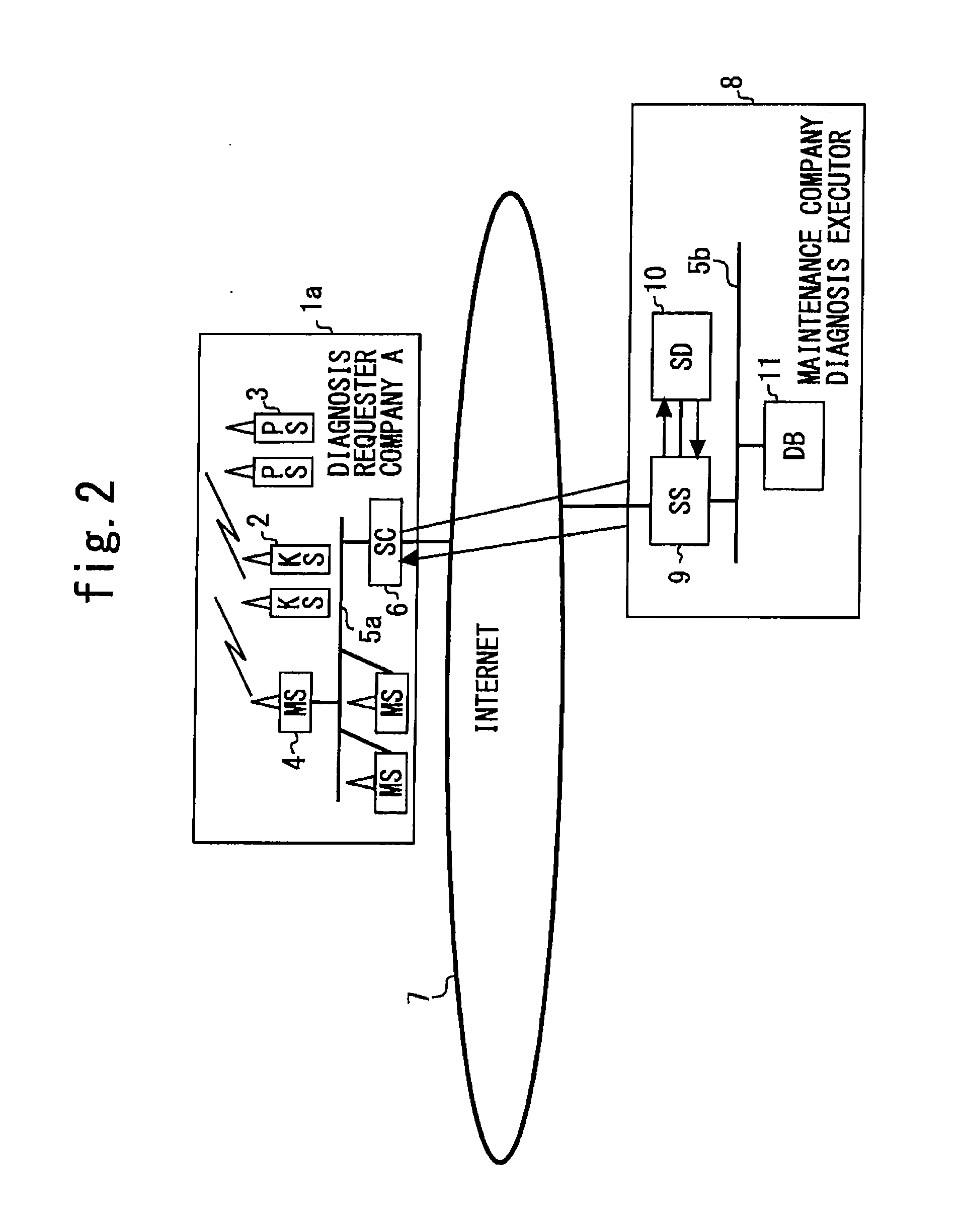
[0058]FIG. 2 is related to Embodiment 2 of the present invention and is a diagram explaining the general configuration of an automatic remote monitoring and diagnosis system.

[0059]Embodiment 2 described here is obtained by paying attention, in particular, to saving and providing measured environmental data in Embodiment 1 described above.

[0060]That is, in the automatic remote monitoring and diagnosis system of the present application invention described in Embodiment 1, as shown in FIG. 2, the diagnostic client 6 and the diagnostic server 9 are communicatably connected by the Internet 7. Therefore, it is possible to continuously send measurement data from the diagnostic client 6 to the diagnostic server 9 at prescribed time intervals. And for this reason, it is possible to continuously retain measurement data from the start of data measurement up to the present time in the data retaining device 10 on the diagnostic server 9 side.

[0061]Company A 1a, which is a measurement and diagnos...

embodiment 3

[0066]FIG. 3 is related to Embodiment 3 of the present invention and is a diagram explaining the general configuration of an automatic remote monitoring and diagnosis system.

[0067]Embodiment 3 described here is obtained by paying attention, in particular, to carrying out an environmental diagnosis, preparing an environmental diagnosis report, and presenting a remedy based on the environmental diagnosis report as well as identifying the cause when an unexpected and sporadic problem occurs and presenting a remedy for the problems in question in Embodiment 1 described above.

[0068]That is, in the automatic remote monitoring and diagnosis system of the present application invention, as described in Embodiment 1, the diagnostic server 9 can carry out an environmental diagnosis of the electronic control devices and the like of a diagnosis requester based on the measurement data sent from the diagnostic client 6 via the Internet 7. Incidentally, in this environmental diagnosis, threshold va...


PUM


Abstract

An automatic remote monitoring and diagnosis system includes an environmental sensor and a physical sensor which measure environmental data and physical data, respectively, on electronic control devices and send the data by wireless communication, a wireless server which collects the measurement data of the sensors, a diagnostic client connected to the wireless server by a first communication network and that collects the measurement data from the wireless server, a diagnostic server connected to the diagnostic client by a second communication network and that carries out a diagnosis based on the measurement data from the diagnostic client, a data retaining device which retains the measurement data, and a knowledge database which stores information necessary for the diagnosis. The diagnostic server sends results of the diagnosis and a remedy to the diagnostic client via the second communication network.

Description

TECHNICAL FIELD[0001]The present invention relates to an automatic remote monitoring and diagnosis system.BACKGROUND ART[0002]For example, electronic control devices for plant equipment or equipment of plants and the like (hereinafter referred to as “electronic control devices and the like”) are affected by the installation environment during the use thereof and troubles and abnormalities may sometimes occur. Therefore, it becomes necessary to carry out an investigation of the installation environment of electronic control devices and the like. In general, this investigation of the installation environment has hitherto been performed at some specific point of time, for example, before the delivery of equipment including electronic control devices, during the installation of equipment, at periodical inspection of equipment, and in the case where some inconvenience occurred unexpectedly in electronic control devices and the like. The measuring period of various kinds of data in this i...

Claims


Application Information

Patent Timeline
Patent Type & Authority Applications(United States)
IPC IPC(8): G06F17/00
CPCG05B2219/13G06F2213/0038G05B23/0275G06F17/00H04M3/5166G05B2223/06G05B23/02G06F13/00G06Q50/10
Inventor MAEHATA, NORIYUKIMATSUDA, SHIGEHIKO
Owner TOSHIBA MITSUBISHI-ELECTRIC IND SYST CORP
Why Eureka
Try Eureka