Ink curing apparatus and method

a curing apparatus and temperature technology, applied in the field of temperature curing apparatus and method, can solve the problems of inability to maintain the curing temperature of the dryer, and the size of the gas dryer to handle the higher volume of product produced by the new generation of industrial digital printers, so as to reduce the bleeding of garment dye to the ink. , the effect of raising the temperature of the ink

Active Publication Date: 2018-07-03
BROWN MFG GRP
View PDF28 Cites 0 Cited by
  • Summary
  • Abstract
  • Description
  • Claims
  • Application Information

AI Technical Summary

Benefits of technology

[0009]A conveying surface may be provided to convey articles past a controlled area controlled by the control from an upstream location toward a downstream location. The control area may include the plurality of heating elements. The heating elements at the upstream location may have a higher wattage than heating elements at the downstream location. An entrance sensor senses an object on the conveying surface entering the controlled area. The entrance sensor may be a photo sensor including a light beam directed across an entrance to the controlled area. The control may energize the heating elements only when an object is present.
[0012]A method of curing ink applied to a fabric, according to an aspect of the invention, includes applying radiant heat to the article while monitoring thermal radiation. Radiant heat is applied at a rate sufficient to raise the temperature of the ink at a rate faster than the temperature of the fabric. Radiant heat is reduced when the temperature of the ink reaches the cure temperature and before the temperature of the fabric reaches the dye migration temperature in order to reduce bleeding of garment dye to the ink.

Problems solved by technology

Known IR dryers cannot maintain the cure temperature for the amount of time required by the new inks, and gas dryers must be too large to handle the higher volume of product produced by the new generation of industrial digital printers.

Method used


Image

  • Ink curing apparatus and method
  • Ink curing apparatus and method
  • Ink curing apparatus and method

Examples


Embodiment Construction

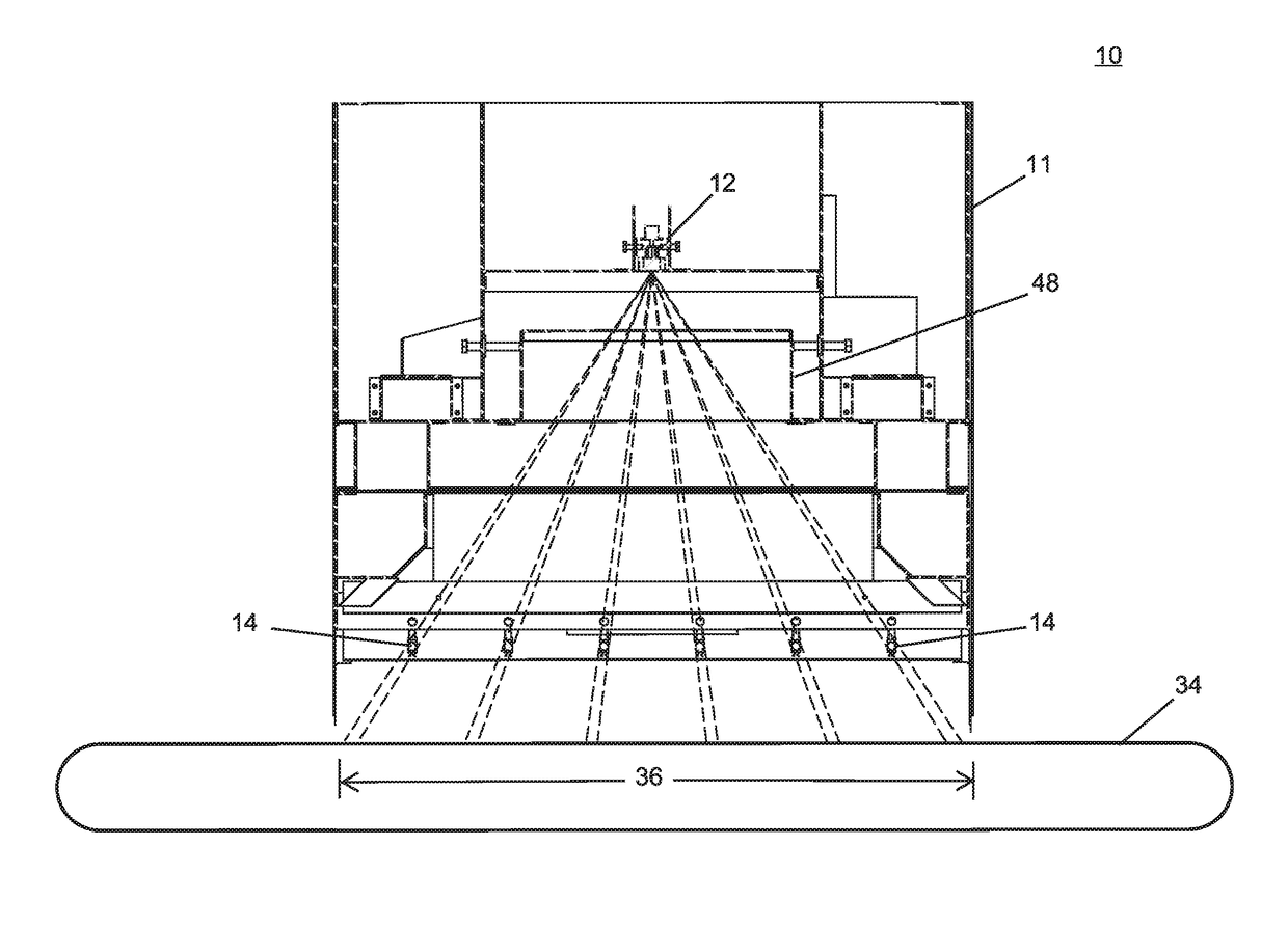
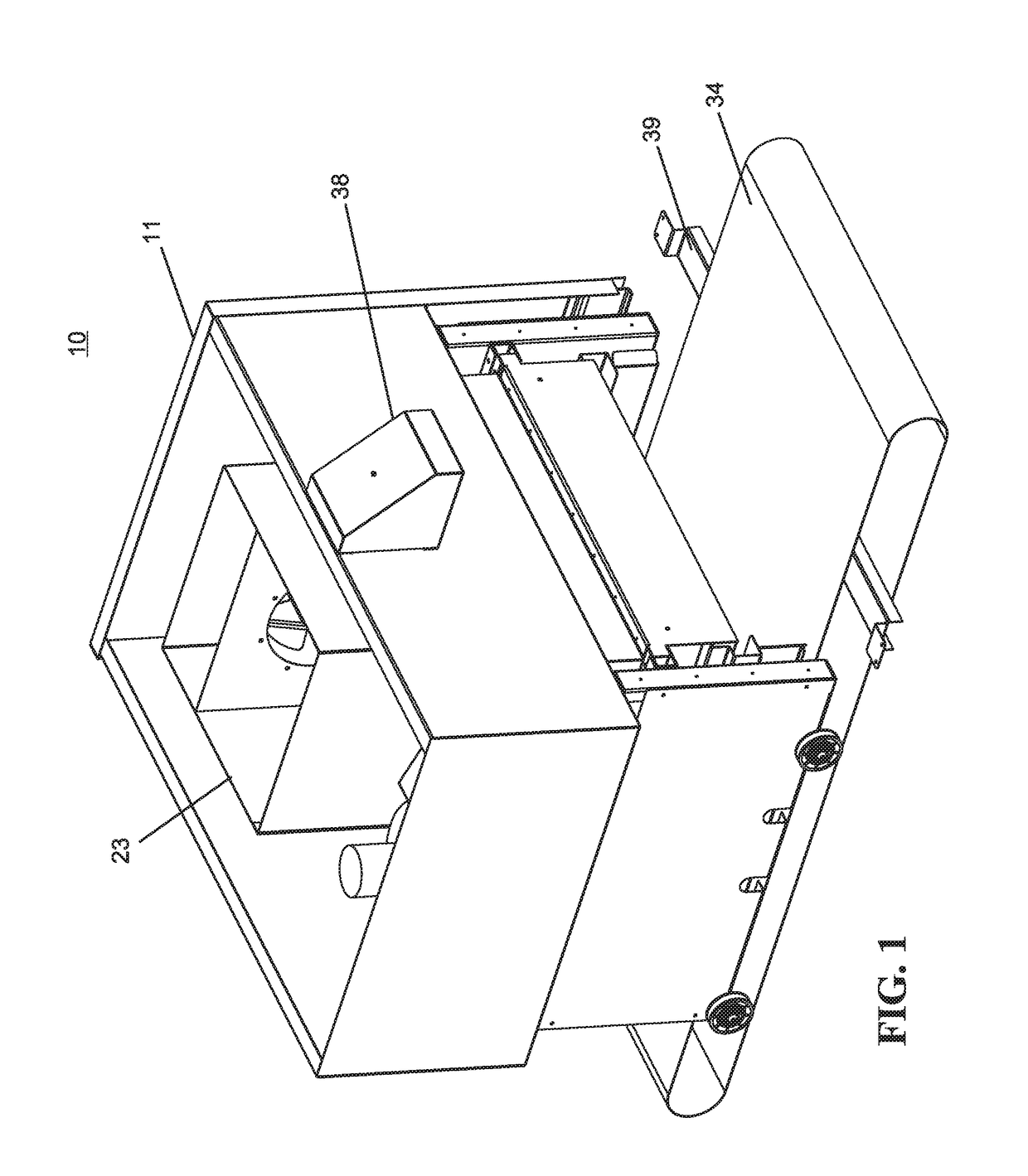
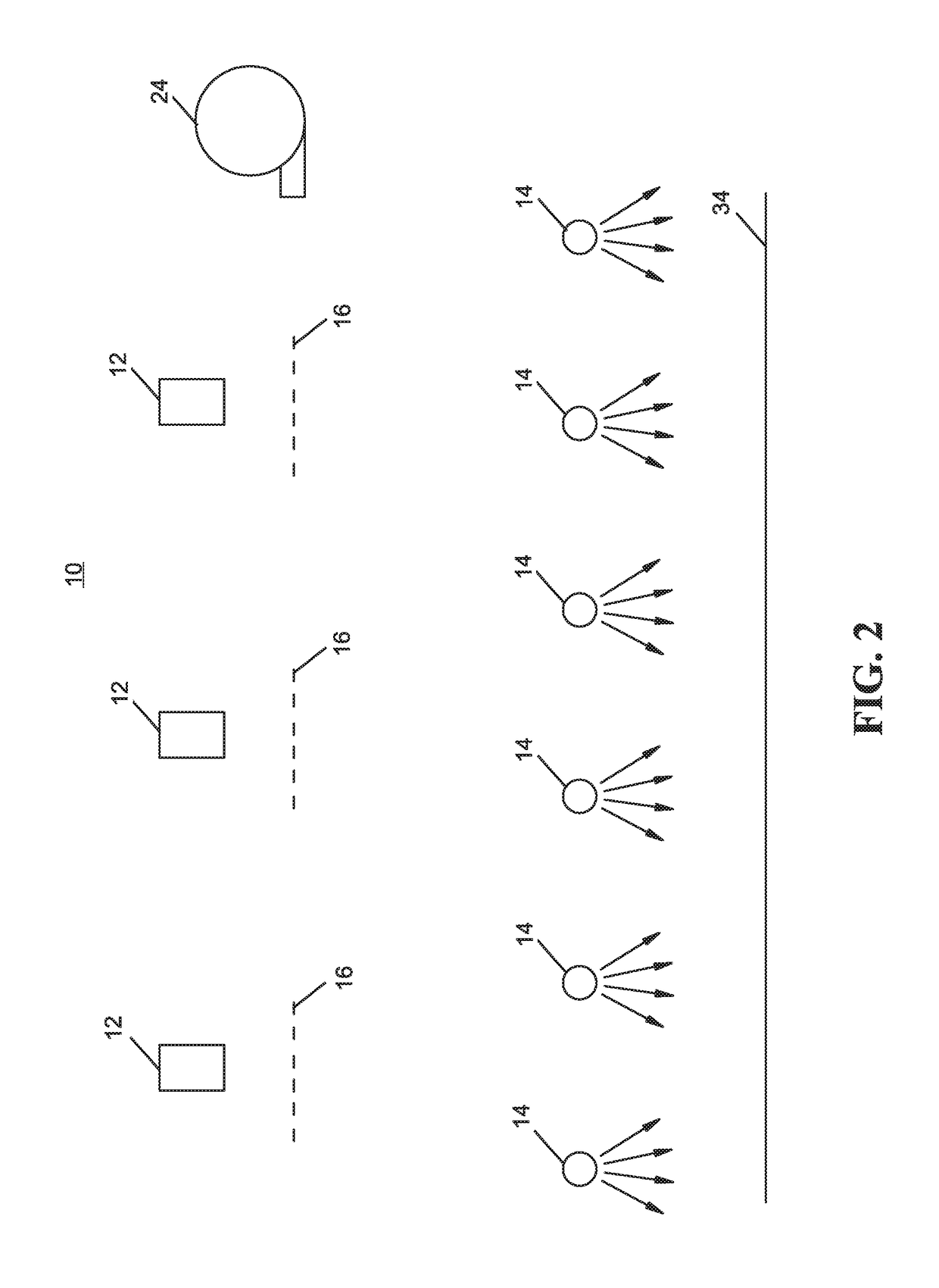
[0033]Referring now to the drawings and the illustrative embodiments depicted therein, a heating apparatus 10 is for heating an object according to a given temperature profile and includes a housing 11 housing one or more thermal imaging sensors 12 that are configured to image thermal radiation of an object, such as a textile object that is digitally printed with ink or with ink otherwise applied. Apparatus 10 further includes one or more heating elements 14 between the imaging sensors 12 and the object, each heating element 14 configured to generate heat energy. In the illustrated embodiment, heating elements 14 are infrared lamps, such as quartz heating elements that have a color temperature in a range from about 1700K to about 1900K. As will be described in more detail below, heating elements 14 are controlled as a function of surface radiation of the object subjacent each particular heating element or combination of adjacent heating elements. A selected number of adjacent heatin...


PUM

PropertyMeasurementUnit
temperatureaaaaaaaaaa
color temperatureaaaaaaaaaa
diameteraaaaaaaaaa

Abstract

An ink curing apparatus for curing ink on an object and method includes at least one thermal imaging sensor that is configured to image thermal radiation of the object and at least one heating element that is configured to generate heat energy. A control responsive to the imaging sensor controls the heating element. The control controls the heating element as a function of the thermal radiation of the object to heat the object to a particular radiation level. The method may be used to cure ink on the object. The object may be made of a textile. The method may be used with at least one chosen from screen printing, digital printing, sublimation ink printing, discharge ink printing, and pad printing.

Description

CROSS REFERENCE TO RELATED APPLICATION[0001]This application claims the priority benefits of International Patent Application No. PCT / US2015 / 015321, filed on Feb. 11, 2015, which claims priority from U.S. patent application Ser. No. 61 / 939,515, filed on Feb. 13, 2014, the disclosures of which are hereby incorporated herein by reference in their entirety.BACKGROUND OF THE INVENTION[0002]The present invention is directed to a temperature curing apparatus and method. While the invention is described with respect to curing ink on a fabric, it is capable of other applications including other types of ink printing, food preparation, plastic forming, and the like.[0003]Many inks require a certain amount of heat in order to cure. In most print shops, products are produced on a continuous basis at ever-increasing speeds. Traditional curing methods have employed heat presses, drawer dryers, and tunnel dryers. However, as the printing machinery capacity has increased, the associated capacity o...

Claims


Application Information

Patent Timeline
Patent Type & Authority Patents(United States)
IPC IPC(8): B41J11/02B41J11/00D06P5/20B41M7/00B41J3/407
CPCB41M7/009D06P5/2077B41J11/002B41J3/4078B41J11/00216
Inventor BROECKERT, HANS P.HARPOLD, STEPHEN M.
Owner BROWN MFG GRP
Why Eureka
Try Eureka