Polarity test of fiber arrays based on electronically switched optical signals

a technology of electronic switching and optical signals, applied in the field of optical communication, can solve problems such as the method of identifying these errors, the assembly process is meeting challenges, and the human error occurs in assembling or manufacturing arrays of fibers, so as to avoid obscuring the purpose

Active Publication Date: 2018-07-03
ALLIAN FIBER OPTIC PROD INC
View PDF19 Cites 10 Cited by
  • Summary
  • Abstract
  • Description
  • Claims
  • Application Information

AI Technical Summary

Benefits of technology

[0004]This section is for the purpose of summarizing some aspects of the present invention and to briefly introduce some preferred embodiments. Simplifications or omissions may be made to avoid obscuring the purpose of the section. Such simplifications or omissions are not intended to limit the scope of the present invention.

Problems solved by technology

As VCSEL and ribbon fiber-based parallel communications become increasingly the dominant low cost solution for high speed short-reach data links, assembly processes are meeting challenges.
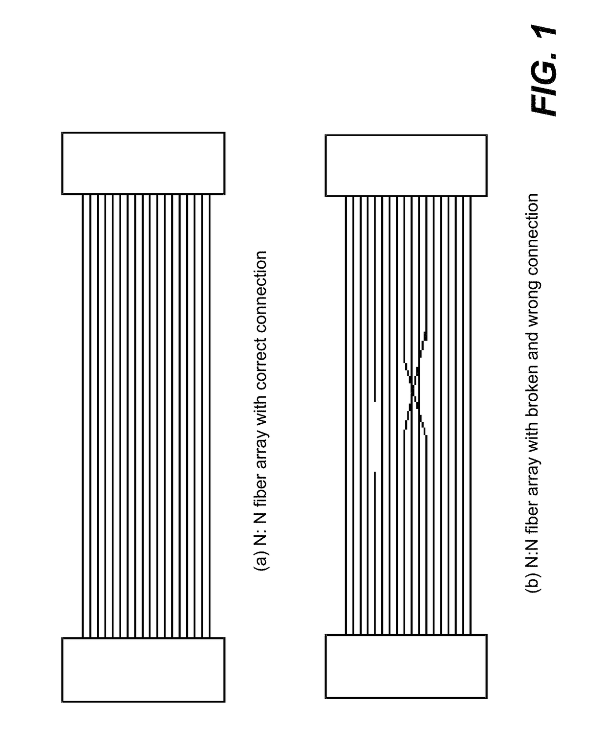
Human errors do occur in assembling or manufacturing arrays of fibers.
Once errors happen, the methods of identifying these mistakes (e.g., polarity error) are often time consuming.

Method used


Image

  • Polarity test of fiber arrays based on electronically switched optical signals
  • Polarity test of fiber arrays based on electronically switched optical signals
  • Polarity test of fiber arrays based on electronically switched optical signals

Examples


Embodiment Construction

[0018]In the following description, numerous specific details are set forth in order to provide a thorough understanding of the present invention. However, it will become obvious to those skilled in the art that the present invention may be practiced without these specific details. The description and representation herein are the common means used by those experienced or skilled in the art to most effectively convey the substance of their work to others skilled in the art. In other instances, well-known methods, procedures, components, and circuitry have not been described in detail to avoid unnecessarily obscuring aspects of the present invention.

[0019]Reference herein to “one embodiment” or “an embodiment” means that a particular feature, structure, or characteristic described in connection with the embodiment can be included in at least one embodiment of the invention. The appearances of the phrase “in one embodiment” in various places in the specification are not necessarily al...


PUM


Abstract

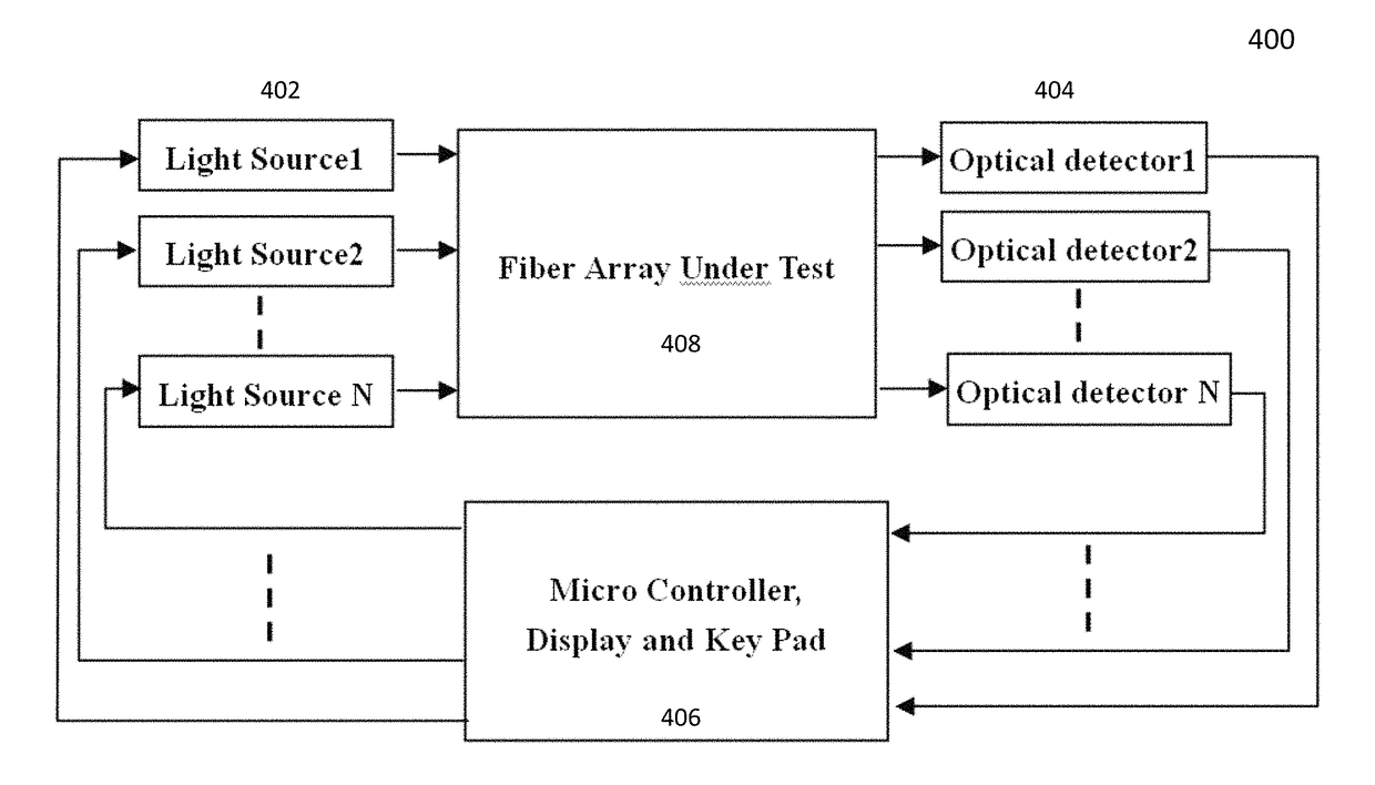
A design of optical testing device or system for fiber arrays is disclosed. According to one aspect of the invention, an array of light sources and an array of detectors are disclosed. One of the light sources is controlled to be turned on to test a designated fiber in an array of fibers being tested for connection issues. A microcontroller is configured to determine which one of the detectors is detecting a light beam from one of the light sources, and mark a channel of the array of fibers accordingly depending on if the one of the detectors is supposed to detect the light beam; if another one of the detectors detects the light beam; or if none of the detectors detects the light beam.

Description

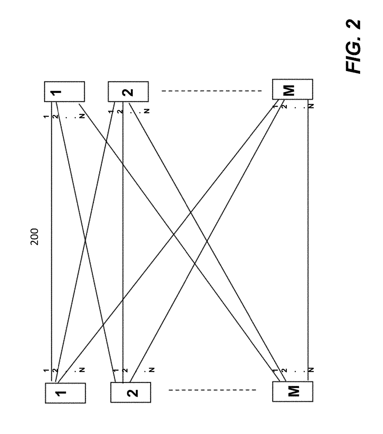
BACKGROUND OF THE INVENTIONField of the Invention[0001]The invention is generally related to the area of optical communications. In particular, the invention is related to polarity test of fiber arrays based on electronically switched optical signals.The Background of Related Art[0002]With advanced development of fiber optical communication technologies, more and more applications of fiber arrays for parallel communications and interconnects are being explored. Vertical Cavity Surface Emitting Lasers (VCSEL) are commonly used in laser arrays in 1D or 2D. The current technologies can allow each such laser to be modulated to carry >10 Gbps data so that an aggregate of >100 Gbps can be transmitted by 10 such lasers in a linear array. At the same time, fiber connectors are making technological breakthroughs that allow many fibers to be ribonized and to be interfaced through a common connector. One typical such connector technology is called MPO connector and it allows 12 such fibe...

Claims


Application Information

Patent Timeline
Patent Type & Authority Patents(United States)
IPC IPC(8): G02B6/04G01M11/00G02B6/42
CPCG01M11/3136G01M11/33G02B6/4249G02B6/4292
Inventor WANG, XINZHONGLI, YAO
Owner ALLIAN FIBER OPTIC PROD INC
Why Eureka
Try Eureka