
Gas monitoring system and gas monitoring method

a gas monitoring system and gas monitoring technology, applied in fluid tightness measurement, instruments, electric devices, etc., can solve the problems of not being able to continuously detect hydrogen concentration at all times, unable to achieve continuous detection of hydrogen concentration, complex electric wiring of vehicles, etc., to achieve easy management of parts or components, avoid delays in detecting abnormal conditions, and improve the merchantability of gas monitoring system and method

Active Publication Date: 2018-07-03
HONDA MOTOR CO LTD
View PDF13 Cites 0 Cited by
  • Summary
  • Abstract
  • Description
  • Claims
  • Application Information

AI Technical Summary

Benefits of technology

The present invention provides a gas monitoring system and method that allows multiple gas sensors to be connected to one trunk line and easily identified through their specifications. This simplifies the process of inspecting and monitoring gas sensors during production.

Problems solved by technology

However, in the technique disclosed in JP2006-071413A, since a large number of gas channels including pipes for gas leakage detection are provided in the vehicle in a complicated manner, an assembly step for this operation and substantial maintenance costs are required.
Further, in the technique disclosed in JP2006-071413A, since one hydrogen sensor is switched in order to detect the hydrogen concentration at a plurality of positions, it may not be possible to detect the hydrogen concentration continuously at all times due to the switching interval of the fluid passage switching device such as the rotary valve.
Therefore, the electric wiring for the vehicle becomes complex, a substantial number of steps for wiring operations are required, and substantial maintenance costs are required.
However, in a gas monitoring system that requires a plurality of gas sensors each having the same function and which are electrically connected to a serial communication bus line (harness), such as the above-described hydrogen sensors, although in terms of component costs and component management costs, it is desirable to use gas sensors having a single specification (same external appearance, same internal structure) as standard parts (general purpose parts), a technique has not yet been established for identifying a plurality of gas sensors, each of which is connected to a bus line for carrying out serial communications.

Method used


Image

  • Gas monitoring system and gas monitoring method
  • Gas monitoring system and gas monitoring method
  • Gas monitoring system and gas monitoring method

Examples


Embodiment Construction

[0038]Hereinafter, a preferred embodiment of a gas monitoring system according to the present invention will be described in detail below with reference to the accompanying drawings.

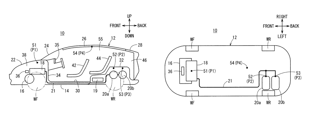
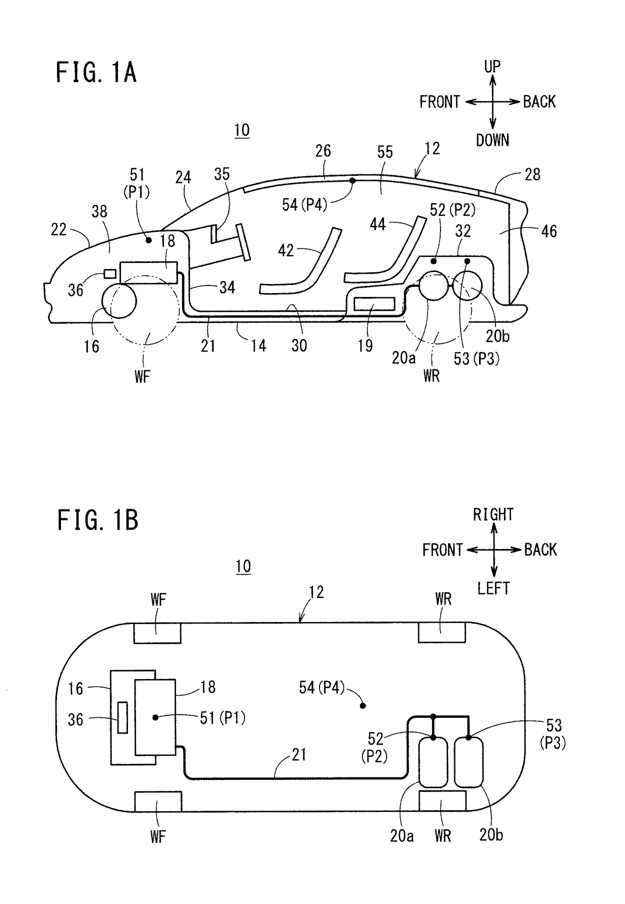
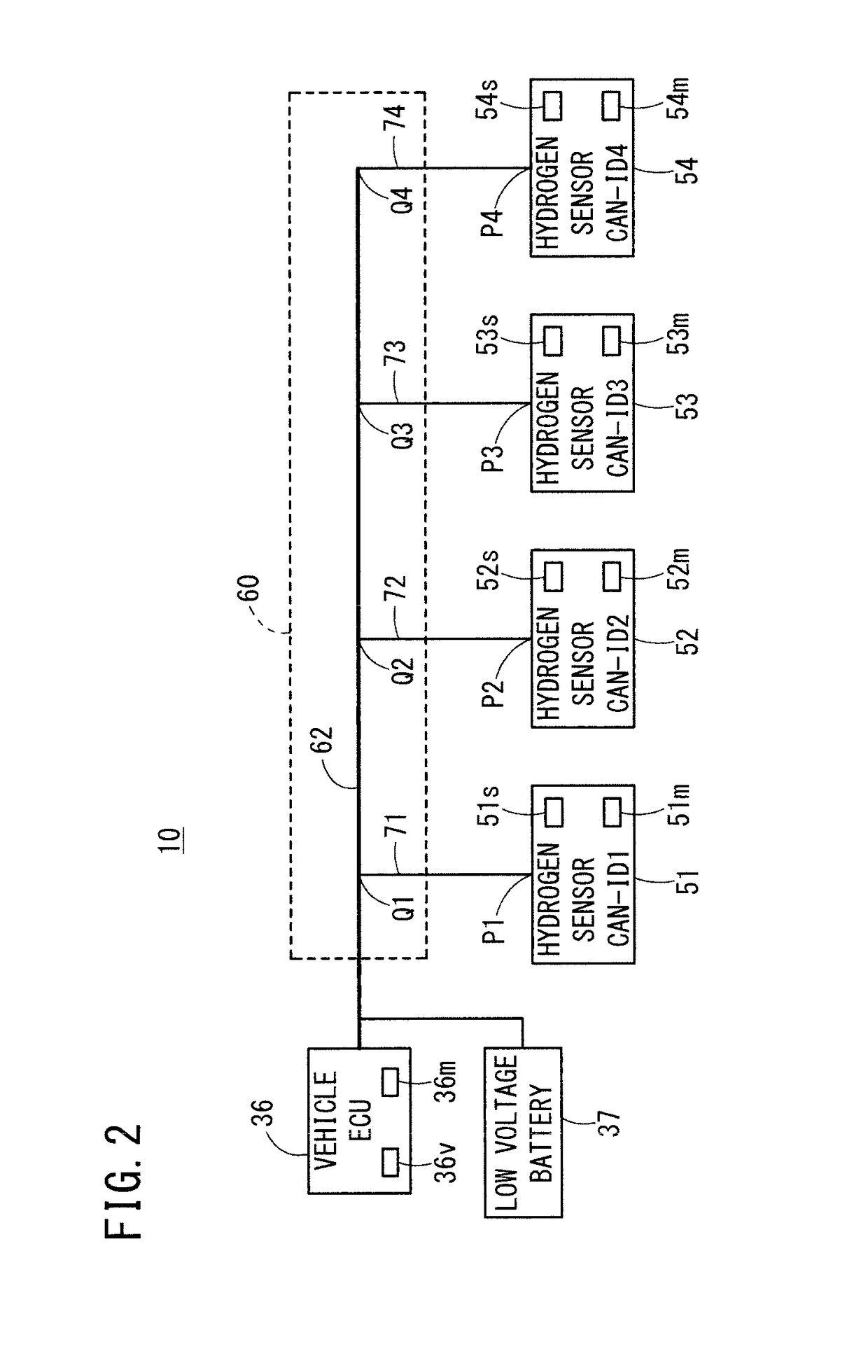
[0039]FIG. 1A is a side view schematically showing the structure of a fuel cell vehicle 12, which is equipped with a gas monitoring system for carrying out a gas monitoring method according to the present embodiment. FIG. 1B is a plan view schematically showing the structure of the fuel cell vehicle 12. FIG. 2 is a circuit block diagram showing the gas monitoring system 10.

[0040]As shown in FIGS. 1A and 1B, the fuel cell vehicle 12 includes a base frame 14. Components such as front wheels WF, rear wheels WR, a traction motor 16 for driving the front wheels WF, a fuel cell stack 18, hydrogen tanks 20a, 20b, a pipe 21, and a battery 19 (high voltage battery) are supported directly, or through structural bodies, on the base frame 14. In the following description, a front-back direction, a left-right directi...


PUM

PropertyMeasurementUnit
concentrationaaaaaaaaaa
distanceaaaaaaaaaa
structureaaaaaaaaaa

Abstract

A gas monitoring system and a gas monitoring method make it possible to identify plural gas sensors having a single specification and which are connected to one trunk line. Trunk line connectors have identification configurations for allowing information concerning positions where the trunk line connectors to be identified are arranged. Hydrogen sensors have a single specification (the same specification). When connectors of the hydrogen sensors are fitted to the trunk line connectors, the hydrogen sensors store the sensor IDs, which are assigned to the hydrogen sensors, in memory units based on the identification configurations of the trunk line connectors.

Description

CROSS-REFERENCE TO RELATED APPLICATION[0001]This application is based upon and claims the benefit of priority from Japanese Patent Application No. 2014-090871 filed on Apr. 25, 2014, the contents of which are incorporated herein by reference.BACKGROUND OF THE INVENTION[0002]Field of the Invention[0003]The present invention relates to a gas monitoring system using a plurality of gas sensors (e.g., hydrogen sensors), and further relates to a gas monitoring system and a gas monitoring method that can be applied suitably to a fuel cell vehicle, etc.[0004]Description of the Related Art[0005]In recent years, green wave activities have been proposed, e.g., from the standpoint of reducing CO2 emissions, etc. To this end, environmentally friendly fuel cell vehicles are drawing attention.[0006]In Japanese Laid-Open Patent Publication No. 2006-071413 (hereinafter referred to as JP2006-071413A), in relation to a fuel cell vehicle equipped with a fuel cell system, the necessity of detecting hydr...

Claims


Application Information

Patent Timeline
Patent Type & Authority Patents(United States)
IPC IPC(8): G01M3/00G01N33/00B60L11/18
CPCG01N33/0027G01M3/00B60L11/1881B60L3/0053B60L58/30Y02T90/40
Inventor SUZUKI, AKIHIROKAWAURA, TAKASHI
Owner HONDA MOTOR CO LTD
Learn More