

Method and device for inspecting patterned medium
a technology of patterned medium and inspection method, which is applied in the direction of optical radiation measurement, instruments, spectrometry/spectrophotometry/monochromators, etc., can solve the problems of lowering the inspection/measurement accuracy, and affecting the accuracy of inspection
- Summary
- Abstract
- Description
- Claims
- Application Information
AI Technical Summary
Benefits of technology
Problems solved by technology
Method used
Image

Examples
first embodiment
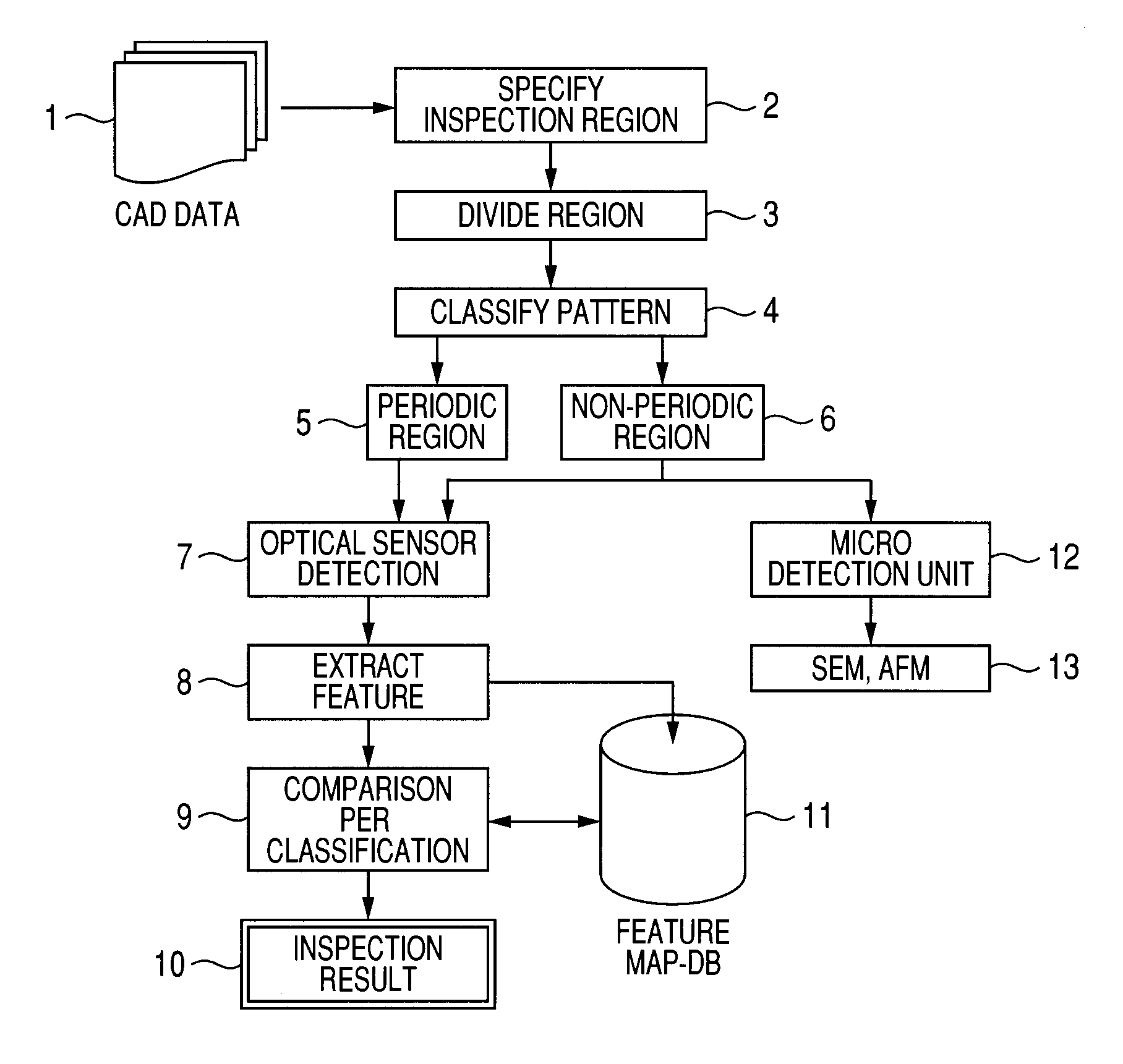
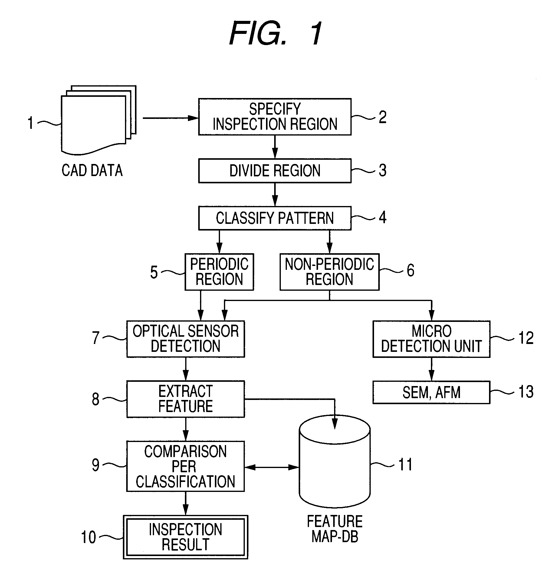
[0045]FIG. 1 shows an operation flow of the patterned medium inspection according to the present invention.
[0046]The region on the sample required to be inspected is specified using CAD data 1 as the design information which contains the pattern shape and dimension of the patterned medium as an object for inspection. The region specified by inspection region specification 2 is divided into regions each of which is evaluated through region division 3. The number of the divided regions from the specified region is sufficiently large to allow observation of the distribution feature of the inspection object.
[0047]The division per evaluation unit has a hexagonal shape as shown in FIG. 4 in the form of the optical spot, for example. The divided region has the diameter of approximately several μms. The division per evaluation unit has the hexagonal shape as shown in FIG. 4. However, it may have a circular or any other shape.
[0048]A pattern classification 4 is performed for each divided reg...
second embodiment
[0068]The center of the pattern formed on the patterned medium disk does not necessarily accord with the center of the rotating disk. Generally, eccentricity exists between those centers. The magnetic head for detection is designed to follow up the eccentricity. In the case where the eccentricity becomes greater to exceed the limit of the follow-up capability, it is important to simplify the evaluation with respect to the level of the eccentricity between the rotating center and the center of the magnetic pattern.
[0069]The present invention may be applied to realize the aforementioned object. An evaluation example according to the present invention will be shown in FIG. 9. Referring to FIG. 9, a sample 72 is placed on a stage 71 which turns around a rotating axis 70 with respect to a detection optical system 73 for detecting the optical feature. When the axis 70 is moved in the direction r, the entire surface area of the sample may be scanned. This scan is called rθ scanning.
[0070]T...
third embodiment
[0076]In the first embodiment, the divided region 40 is identical to the detection region detected by the optical sensor. However, they do not have to be conformed to. The patterned medium has the pitch of approximately 25 nm, and the detection region to be detected by the optical sensor has the pitch of several μm. The resultant pitch difference is double-digit. There may be the case that the detection requires the pitch smaller than that of the detection region detected by the optical sensor.
[0077]In such a case, a measurement pitch 81 of the detection region 80 detected by the optical sensor is decreased as shown in FIG. 11. The detection resolution in the planar direction is increased to allow accurate measurement of the pattern layout and the eccentric amount.
[0078]Meanwhile, if the measurement pitch 81 is decreased, the measurement needs longer time. When the high-speed inspection is prioritized to the increase in the planar resolution, the measurement pitch 81 is made larger ...
PUM
 Abstract
Description
Claims
Application Information