Method and a device for calculating a safe path from the current position of an aircraft to an attachment point

a technology of safe path and current position, applied in the direction of process and machine control, navigation instruments, instruments, etc., can solve the problems of short time, inability to calculate safe path, and inability to take into account the topography of the terrain or the presence of obstacles

Inactive Publication Date: 2018-07-03
EUROCOPTER
View PDF20 Cites 0 Cited by
  • Summary
  • Abstract
  • Description
  • Claims
  • Application Information

AI Technical Summary

Benefits of technology

[0025]An object of the present invention is to avoid the above-mentioned limitations and to propose a method and a device suitable for defining quickly and automatically a path that enables the aircraft at any time to reach a previously defined point safely, e.g. a point selected by the crew of the aircraft.

Problems solved by technology

Nevertheless, during the flight, the aircraft may be diverted and thus leave the initial route under particular circumstances.
Furthermore, in the context of military missions, the aircraft may have only a short time in which to rejoin its initial route.
Nevertheless, such a flight plan may be sparse or even non-existent, due to lack of knowledge about the terrain in that zone.
Furthermore, in the context of military missions, the path of the aircraft often needs to involve low altitude flight in order to limit detection and vulnerability of the aircraft.
However, this path takes no account of the topography of the terrain or of the presence of obstacles.
As a result, this “direct-to” function is not safe and is therefore not suitable for all types of terrain, in particular in the presence of a hill, of obstacles, or indeed of mountainous relief.
Nevertheless, this safe 3D path is not optimized.
In particular, this safe 3D path allows for relief or obstacles to be passed solely by passing over them, but does not make any proposal for going round them on a horizontal path that might be better suited to the capabilities and the performance of the aircraft or to the discretion that is required for military missions.
This function also represents a considerable workload for the crew of the aircraft, since there can sometimes be as many as fifty operations to perform.
Drawing up this new route thus takes a relatively long time.
Nevertheless, that path is situated in a horizontal plane that contains the current position of the aircraft and the designated point, and it is therefore not safe and suitable for all types of terrain.

Method used


Image

  • Method and a device for calculating a safe path from the current position of an aircraft to an attachment point
  • Method and a device for calculating a safe path from the current position of an aircraft to an attachment point
  • Method and a device for calculating a safe path from the current position of an aircraft to an attachment point

Examples


Embodiment Construction

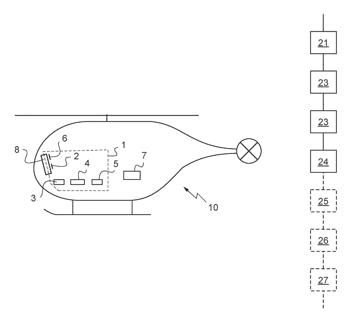
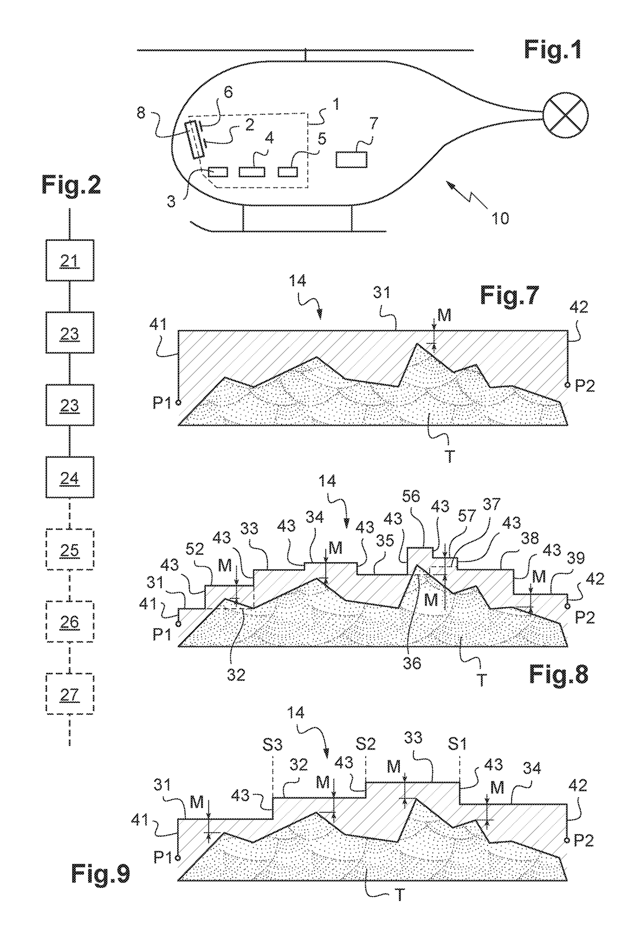
[0087]FIG. 1 shows a rotary wing aircraft 10 having a device 1 for calculating a safe path for flying over terrain, an instrument panel 8, and an autopilot 7. The device 1 includes a man-machine interface MMI 2, display means 6, locating means 5 for locating the aircraft 10, a database 4 containing “terrain” and / or obstacles, and a calculator 3.

[0088]FIG. 2 is a block diagram summarizing a method of calculating a safe path for flying over terrain from the current position P1 of an aircraft 10 to an attachment point P2. The method comprises four main steps 21-24 that can be performed by the device 1 for calculating a safe path for flight over terrain.

[0089]During a first step 21, a strategy is selected for choosing the attachment point P2 and the type of safe path. This choice is performed by the crew of the aircraft 10, e.g. the pilot, using the man-machine interface MMI 2. This choice may be made at any instant, both while preparing a flight and while in flight.

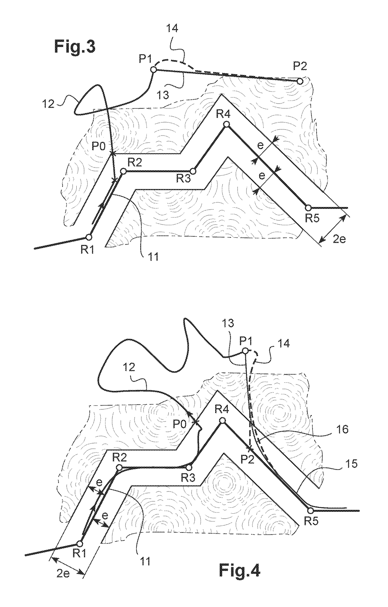
[0090]Examples of va...


PUM


Abstract

A method and device for calculating a safe path from a current position (P1) of an aircraft to an attachment point (P2) over a terrain. The current position (P1) of the aircraft is determined, and then the attachment point (P2) is defined. At least one attachment path connects he current position (P1) to the attachment point (P2) in safe manner over the terrain. The attachment path may be subdivided into a plurality of tracks (31-39). Each track (31-39) is situated at a safe altitude that is higher than the highest point of the terrain being overflown. In addition, the attachment path may be a return path defined by passage points (S1-S8) of the aircraft.

Description

CROSS-REFERENCE TO RELATED APPLICATIONS[0001]This application claims the benefit of FR 15 02454 filed on Nov. 24, 2015, the disclosure of which is incorporated in its entirety by reference herein.BACKGROUND OF THE INVENTION[0002](1) Filed of the Invention[0003]The present invention lies in the field of systems for navigating and managing the flight of an aircraft that covers, among other functions, the functions of preparing a flight plan and of generating a flight path for the aircraft.[0004]The present invention relates to a method of calculating a safe path from the current position of an aircraft to an attachment point, and also to a device for performing the method.[0005](2) Description of Related Art[0006]It should be observed that the term “flight plan” is used to designate a theoretical route to be followed by an aircraft, which theoretical route joins together a plurality of successive waypoints.[0007]In addition, the term “path” is used to mean the track to be followed by ...

Claims


Application Information

Patent Timeline
Patent Type & Authority Patents(United States)
IPC IPC(8): G08G5/00G01C21/00B64D43/00B64C27/04
CPCG08G5/0034B64C27/04G08G5/0047G01C21/00B64D43/00G01C21/20G01C23/00G05D1/0646G08G5/0021G08G5/0091
Inventor GILLET, MARIANNE
Owner EUROCOPTER
Why Eureka
Try Eureka