Dental furnace

a technology for dental objects and furnaces, applied in furnaces, muffle furnaces, lighting and heating apparatus, etc., can solve the problems of difficult to align the sensors according to the facts, the temperature of dental objects cannot be exactly represented, and the attachment of dental objects is not practicable in practi

Active Publication Date: 2019-03-05
IVOCLAR VIVADENT AG
View PDF30 Cites 0 Cited by
  • Summary
  • Abstract
  • Description
  • Claims
  • Application Information

AI Technical Summary

Benefits of technology

[0020]While with a simple temperature sensor normally only a punctiform temperature detection is possible, the two-dimensional temperature detection simultaneously also enables the detection of the temperature distribution. This also enables the identification of the shape, the size, the position, the number and maybe even the type of the dental restoration parts to be processed.
[0023]Prior to the insertion of the dental restoration parts, the thermal imaging camera in case of a furnace with an open hood is directed towards the environment that typically has ambient temperature. If the dental restoration parts—that are usually placed on a firing tray which facilitates the placement and removal thereof—are placed on the furnace floor, it can be detected on the one hand that the hot furnace base has now been covered. In this way the insertion or placement of a firing tray may be detected. In turn, the removal of the firing tray would be detected, because the firing base has a temperature difference compared to the firing tray. The dental restoration parts that are not yet heated during the placement thereof and approximately have the temperature of the environment or the firing tray, respectively, on which they are placed, do not result in a change of the image in the first seconds. Only if the hot furnace hood that extends over the dental restoration parts, and the firing base on which the firing tray with the objects is placed, heats the dental restoration parts to some degree, their outline stands out from the background as a thermal matrix.
[0026]In this way, desired process parameters that may depend on the size, can also and automatically be adjusted in the desired manner. If it is found out for example that there are large and several dental restoration parts, the heating rate, i.e. the desired increase of temperature, may be reduced at the object in order to achieve a gentle and safe drying operation.
[0034]In the same manner it is possible according to the invention to safely reach a pregiven temperature or temperature distribution regardless of the type, number and mass of the dental restoration parts by using the thermal imaging camera with the control and regulating device. This enables a process duration tailored to the needs of the ceramic parts, namely without the safety reserves mentioned at the beginning, and also without taking any risks.
[0044]Typically, the thermal imaging camera is directed such that it is attached to the furnace diagonally back and detects the image thereof in particular diagonally to the front. At the opposite side of the firing chamber—as seen from above of the thermal imaging camera—typically no heat sources are present that could adversely affect the detection by the thermal imaging camera. Heat sources that are present nevertheless, such as a firing furnace that coincidentally is arranged in the viewing direction of the camera, that is opened and that is correspondingly hot, can nevertheless be distinguished from the dental restoration part. This is due to the fact that a foreign heat source has as different temporal course of temperature than the dental restoration parts inserted into the dental furnace according to the invention. The mentioned position of the camera is also favorable because through this it is more difficult for the user to inadvertently insert disturbing objects between the camera and the dental restoration parts that are to be detected.
[0050]If necessary, the inventive thermal imaging camera can also work when the furnace hood is lowered. For this purpose, a viewing window is provided in the firing hood which viewing window is permeable to infrared radiation and allows for the longest possible visual contact with the objects to be measured even at a lowered furnace hood.

Problems solved by technology

Moreover, it has been proposed to use thermal elements that are located in the furnace head or furnace base, namely next to the working area of the dental restoration parts to be processed, but that nevertheless cannot exactly represent the temperature of these objects.
It is difficult to align these sensors according to the facts.
A thermal element would have to be attached to a dental object which is not feasible in practice.
The alternatives described exhibit the disadvantage that an incorrect attachment of the sensor and / or the dental object may result in a large measurement error.
Moreover, the attachment of the sensors is partially difficult, for example if the object has a powdery consistency.
On this occasion, however, a deterioration of the properties of the ceramics used for the firing of the dental restoration part is accepted.

Method used


Image

  • Dental furnace
  • Dental furnace
  • Dental furnace

Examples


Embodiment Construction

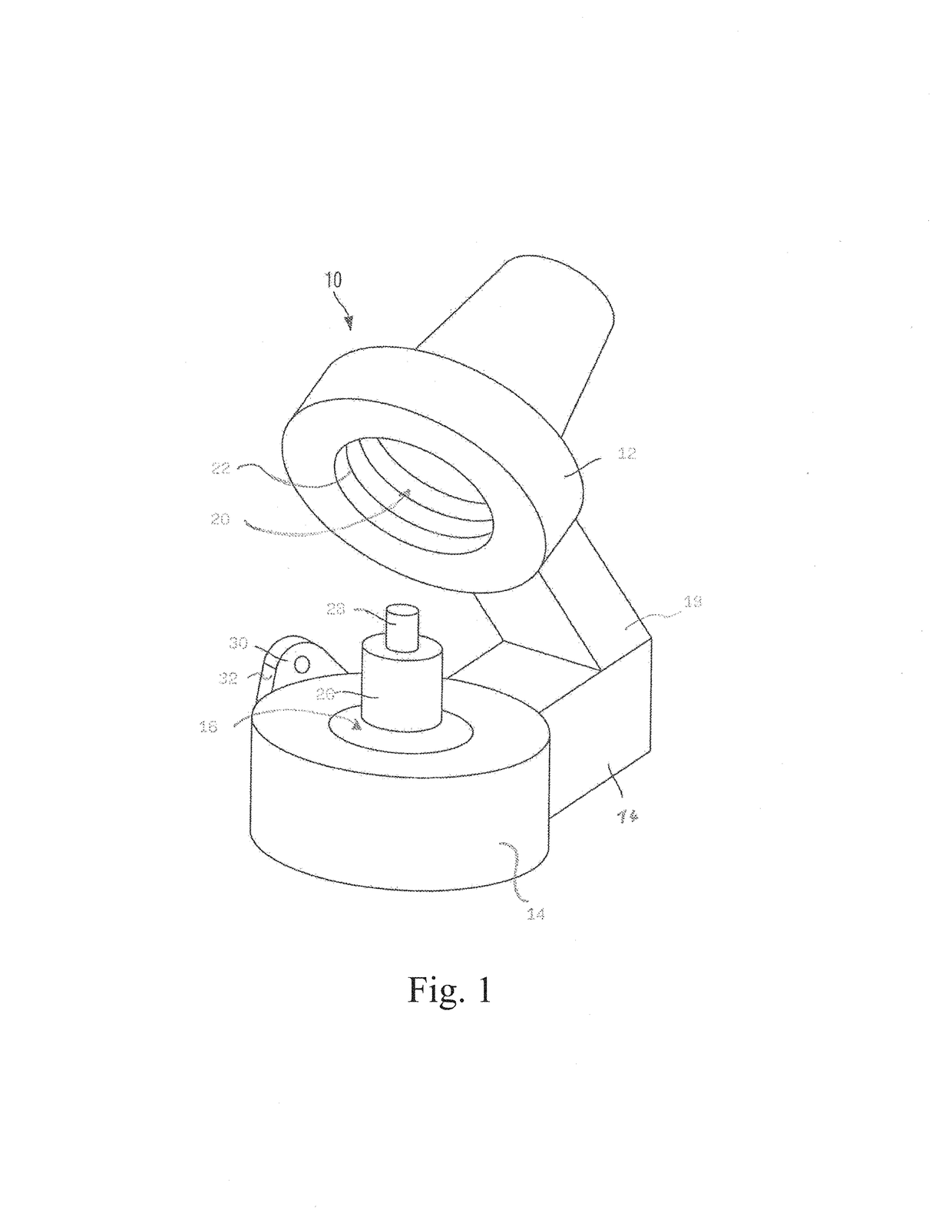
[0076]In FIG. 1 a dental furnace 10 is illustrated which is formed as a press furnace in the exemplary case.

[0077]The furnace comprises a firing hood 12 and a furnace bottom 14 with a firing chamber floor 16. The firing hood 12 is mounted to the furnace bottom 14 via a joint 18 which is not defined in detail and illustrated only schematically to carry out lifting and tilting movements. It is formed in the shape of a hood and therefore surrounds the firing chamber 20. At its periphery it is provided with a firing chamber heating 22 in a way known per se.

[0078]The firing chamber 20 as well as the firing hood 12 are formed in a circular manner, wherein the firing chamber has substantially the shape of a hollow cylinder. Thus, it is suitable for receiving cylindrical muffles which are used for the pressing of dental restoration parts. A muffle 26 of this type is illustrated in FIG. 1 on the firing chamber floor 16. For producing the dental restoration part the muffle is loaded with a kn...


PUM


Abstract

The invention relates to a dental furnace comprising a firing hood equipped with a heating device that is movably supported for the opening and closing of the dental furnace relative to a base intended for receiving a dental restoration part, and further comprising a heat detection device that is directed towards an area above the base, in particular towards one or more dental restoration parts, and further comprising a control or regulating device for the dental furnace that is coupled to the heat detection device, wherein the heat detection device is configured as a thermal imaging camera (30) which is directed towards the area above the base while the firing hood (12) is partially or completely opened, and which feeds an at least two-dimensional image in the form of a matrix of the one or more inserted dental restoration parts (60) to the control or regulating device and / or to a muffle (26) that is intended for the generation of the dental restoration parts (60).

Description

CROSS-REFERENCE TO RELATED APPLICATIONS[0001]This application is a continuation of U.S. patent application Ser. No. 14 / 135,624, filed on Dec. 20, 2013, which is a continuation-in-part of U.S. patent application Ser. No. 14 / 127,609, filed Dec. 19, 2013, which is a National Stage application of International patent application PCT / EP2013 / 051272 filed on Jan. 24, 2013, which claims priority to Chinese patent application No. 201320437085.0, filed on Jul. 22, 2013 and European patent application No. 12152931.7 filed on Jan. 27, 2012, the disclosures of each of which are incorporated herein by reference in their entirety.TECHNICAL FIELD[0002]The invention relates to a dental furnace according to the preamble of claim 1 or 16, respectively, as well as to a process for controlling or regulating a dental furnace according to the preamble of claim 17.BACKGROUND OF THE INVENTION[0003]Firing furnaces for dental purposes have been known for a long time in which dental restoration parts are fired...

Claims


Application Information

Patent Timeline
Patent Type & Authority Patents(United States)
IPC IPC(8): F27B17/00F27B5/14F27D19/00F27B17/02F27B5/18A61C13/20F27D21/00
CPCA61C13/20F27B5/14F27D21/00F27B17/025F27D19/00F27B5/18
Inventor ROHNER, GOTTFRIEDJUSSEL, RUDOLFBROTZGE, MICHAELLORUNSER, JOHANNES
Owner IVOCLAR VIVADENT AG
Why Eureka
Try Eureka