Imaging system

a technology of image processing and barcodes, applied in the field of image processing systems, can solve the problems of reducing the likelihood of user dazzle, affecting the reading of barcodes, and subject to bright lights

Active Publication Date: 2018-07-03
NCR VOYIX CORP
View PDF7 Cites 3 Cited by
  • Summary
  • Abstract
  • Description
  • Claims
  • Application Information

AI Technical Summary

Benefits of technology

[0008]This provides a computationally effective method of producing a composite image, thus speeding up the production of the composite image.
[0010]This provides a high quality image with high levels of contrast and detail.
[0012]This provides a computationally effective method of producing the composite image which increases the speed of production of the image and maintain a low computational load on the processor.
[0025]The software may cause the processor to threshold average brightness levels of areas within at least one of the sequence of captured images and to replace an area of said captured image having an average brightness level in excess of the threshold with a corresponding area from another of the sequence of captured images to produce the composite image.

Problems solved by technology

The integration of an illumination device with an imaging device to increase the light available for imaging an object has a number of problems associated with it, particularly in the case of integrating the illumination and imaging devices within a point-of-sale (POS) barcode scanner.
This has the problem that the user, be that the check-out operative or the customer in the case of a POS barcode scanner, is subject to bright lights which may be strobing due to the illumination device operating only when an image is recorded.
Whilst reducing the likelihood of user dazzle by the illumination device, this arrangement has a number of problems associated with it.
Firstly, a proportion of the light emitted from the illumination device is reflected back from the surface of the window and will enter the aperture of the imaging device, such that it saturates the imaging device.
Accordingly the barcode can be unreadable, causing the object to have to be rescanned.

Method used


Image

  • Imaging system
  • Imaging system

Examples


Embodiment Construction

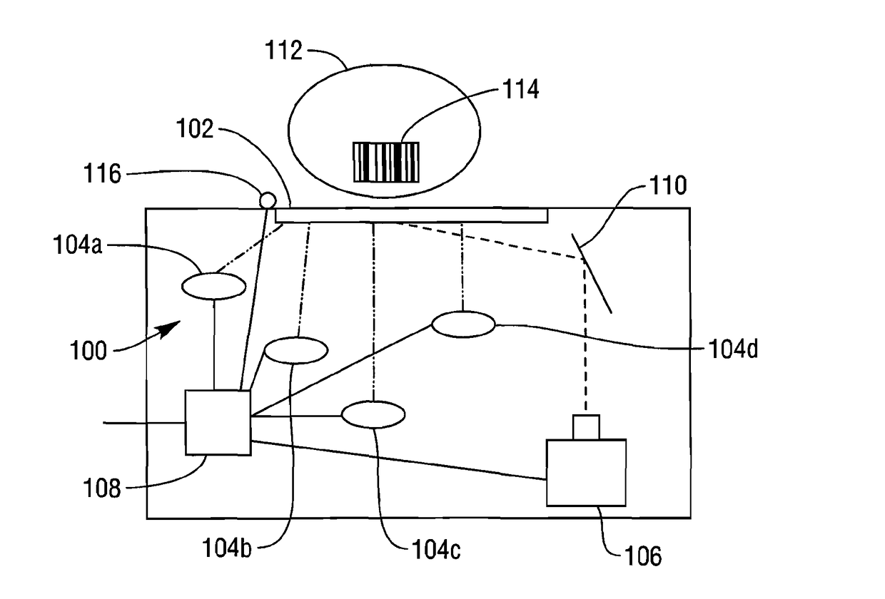
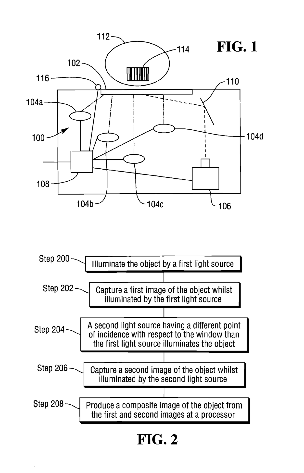
[0030]Referring now to FIG. 1, an imaging POS barcode scanner 100, comprises a transparent window 102, also known as a platen, a plurality of illumination devices 104, a camera 106, a processor 108 and a mirror 110.

[0031]Typically, the illumination devices 104 comprise light emitting diodes (LEDs). Usually LEDs operate in the visible or infra-red parts of the electromagnetic spectrum.

[0032]Usually, the camera 106 comprises a complementary metal oxide semiconductor (CMOS) imaging array or a charge coupled device (CCD) imaging array. The camera 106 can comprise either a one dimensional, linear array of sensing elements or two dimensional array of sensing elements dependent upon the application which the scanner 100 is to be applied to.

[0033]In some embodiments the mirror 110 increases the optical path between the window 102 and the camera 106 such that the focal plane of the camera 106 extends over substantially all of the window 102. In some embodiments, a single mirror reflect the l...


PUM


Abstract

An imaging device comprises a number of light sources, a camera, a processor and a platen. As an object is moved over the platen each of the light sources illuminates the platen sequentially, with the principal axis of illumination of each light source intersecting the plane of the platen at a different place. The camera captures a series of images of the object, each captured image corresponding to the illumination of the platen by a different light source. The processor then generates a composite image from the series of images that compensates for the reflection of light from the platen associated with the principal axis of illumination.

Description

CROSS-REFERENCE TO RELATED APPLICATIONS[0001]The present application claims the benefit of the filing date of Provisional Application Ser. No. 61 / 139,851, filed Dec. 22, 2008, under the same title.FIELD OF THE INVENTION[0002]This invention relates to an imaging system. More particularly, but not exclusively, it relates to an imaging system comprising multiple illumination devices. Even more particularly, but not exclusively, it relates to an imaging system for use in a barcode reader.BACKGROUND TO THE INVENTION[0003]The integration of an illumination device with an imaging device to increase the light available for imaging an object has a number of problems associated with it, particularly in the case of integrating the illumination and imaging devices within a point-of-sale (POS) barcode scanner.[0004]One solution to such an integration is to place the illumination device and the imaging device on opposite sides of a window, or platen. This has the problem that the user, be that th...

Claims


Application Information

Patent Timeline
Patent Type & Authority Patents(United States)
IPC IPC(8): H04N5/262H04N5/265H04N5/225H04N5/232
CPCH04N5/2256H04N5/265H04N5/23232H04N23/56H04N23/951
Inventor ROQUEMORE, III, JOHN P.
Owner NCR VOYIX CORP
Why Eureka
Try Eureka