

Method of moulding a charge
a charge and charge technology, applied in the field of charge moulding, to achieve the effect of reducing wrinkles and superior forming results
- Summary
- Abstract
- Description
- Claims
- Application Information
AI Technical Summary
Benefits of technology
Problems solved by technology
Method used
Image

Examples
Embodiment Construction
)
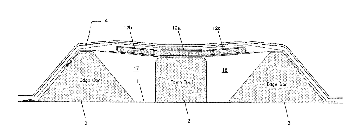
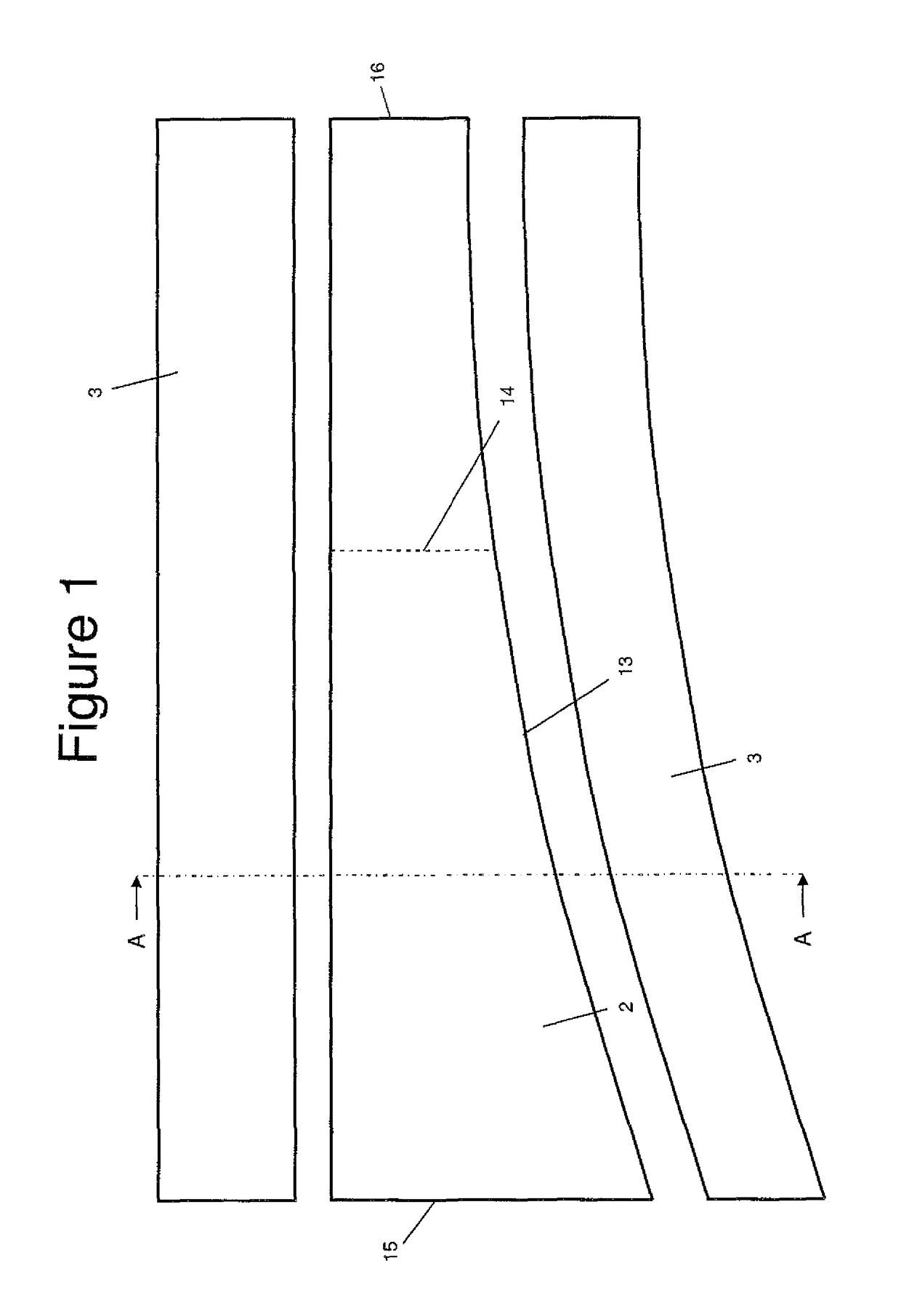
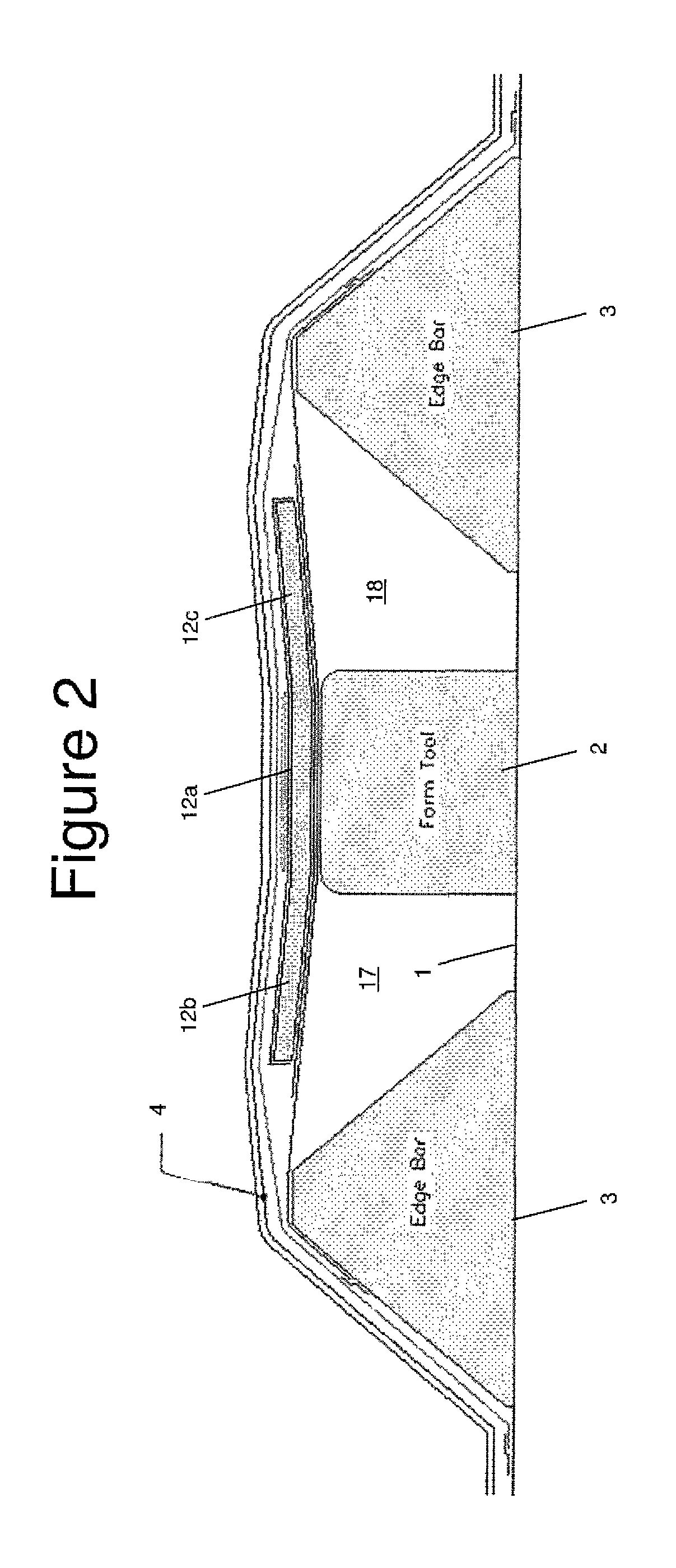
[0032]FIG. 1 is a plan view of a male moulding and debulking tool 2 and a pair of edge bars 3 which are used to form a C-section aircraft spar. FIG. 2 is a sectional view taken along line A-A in FIG. 1. As shown in FIG. 2, the tool 2 and edge bars 3 are mounted on a table 1.
[0033]In a first step, a planar sheet of composite prepreg is formed either by a tape-laying or other automated machine on a planar table (not shown). A planar prepreg charge 12 with the desired shape is then cut from the planar sheet. It will be appreciated that the prepreg charge 12 may be formed from a variety of suitable composite materials. In a preferred embodiment the charge is formed from an epoxy resin reinforced by uniaxial carbon fibres, such as T700 / M21 provided by Hexcel (www.hexcel.com).
[0034]Referring to FIG. 3, a flexible support membrane 8 of Vacfilm 430 is draped over the tool 2 and edge bars 3, and secured to the edge bars 3 by strips of tape 7. Vacfilm 430 is a high stretch elastomeric baggin...
PUM
| Property | Measurement | Unit |
|---|---|---|
| elongation | aaaaa | aaaaa |
| elongation | aaaaa | aaaaa |
| elongation | aaaaa | aaaaa |
Abstract
Description
Claims
Application Information