High load plastic pallet

a high-load, plastic pallet technology, applied in the direction of packaging, transportation and packaging, containers, etc., can solve the problems of occupying a lot of space, affecting the durability of wood pallets, and affecting the use of automated packaging lines

Active Publication Date: 2018-07-10
BURK RYAN
View PDF16 Cites 8 Cited by
  • Summary
  • Abstract
  • Description
  • Claims
  • Application Information

AI Technical Summary

Benefits of technology

[0010]In one embodiment the pallet is a unitary structure which may be the result of a molding process wherein the pallet is of one piece. A unitary structure is not critical to the pallet's design but lends itself well to simplifying both its construction and storage. If molded to provide a hollow or mostly hollow construction, the pallet can be relatively lightweight relative to its solid brethren. For example, some embodiments of the pallet range in weight between about 11 and about 20 pounds. Although not required, the pallet may be of plastic materials, or of composites that include plastic. The structure and material, combined, provides a stronger pallet than prior art pallets made of wood. The pallet of the present invention may be constructed to bear loads up to and including about 2000 pounds or more without undue sag, able to span a 42″ or 44″ inch open pallet rack or comprise differing dimensions, and are semi-stackable and nestable.
[0013]A runner as described herein may span most of the distance between two portions of the deck surface, typically, substantially spanning the distance between two sides or edges. The deck portion may or may not include a lip covering the open space at an end of a runner between the first angled generally planar surface and the second angled generally planar surface, thereby sealing that end of the runner from water, debris, or pests.
[0015]The strength of each runner is accomplished by the use of Z-girts in its construction. Specifically, the first angled generally planar surface and the second angled generally planar surface are formed in a manner that provides the strength of two z-girts placed back-to-back. This shape then provides the advantages expected from the use of z-girts, and allows the load to be spanned to the first and second ends of the runner. Further, in one embodiment, the first lip and the second lip of each runner each forms an integral part of the deck portion. In one embodiment, one of said lips of each of the outermost two of said at least one runners forms an outer edge of said pallet. In an embodiment, each of the ends of each runner is provided with a third and fourth lip, respectively, which lip forms a portion of the outer edge of said pallet. In another embodiment, each lip can be at any one of many different angles from the adjoining angular surface of the “V” runner. For an example of embodiments of the present invention exhibiting these characteristics, see FIGS. 1, 2 and 3.
[0020]A cross runner, ribs, or solid decking may be employed to add strength and rigidity. In some embodiments, a cross runner or rib may run between and be associated with at least two runners. A cross runner may or may not comprise the V / U / flattened V construction.

Problems solved by technology

The transport of objects from one place to another has been a challenge since ancient times. Storage of multiple objects also poses challenges.
Further, wood pallets are not as durable as plastic or metal pallets, and will swell and contract with atmospheric or working conditions, causing issues in their use for automated packaging lines.
A problem with the use of pallets for moving and storing materials is what to do with a pallet when empty.
They often are stacked but take up quite a bit of space and the stack's height is limited in order to prevent shifting and the possibility of a stack of pallets falling on someone.
Adding to the danger, many present pallet designs are heavy in order to accommodate their intended uses, making their empty-stage storage and transfer both cumbersome and expensive.
Although attempts have been made to use plastic pallets for similar loads, the designs of those pallets have been deficient in the amount of sag, and the pallet's durability and load-bearing capability.
Those pallets that adequately address sag and bear adequate weight are often also heavier, requiring more materials to provide adequate functionality.

Method used


Image

  • High load plastic pallet
  • High load plastic pallet
  • High load plastic pallet

Examples


Embodiment Construction

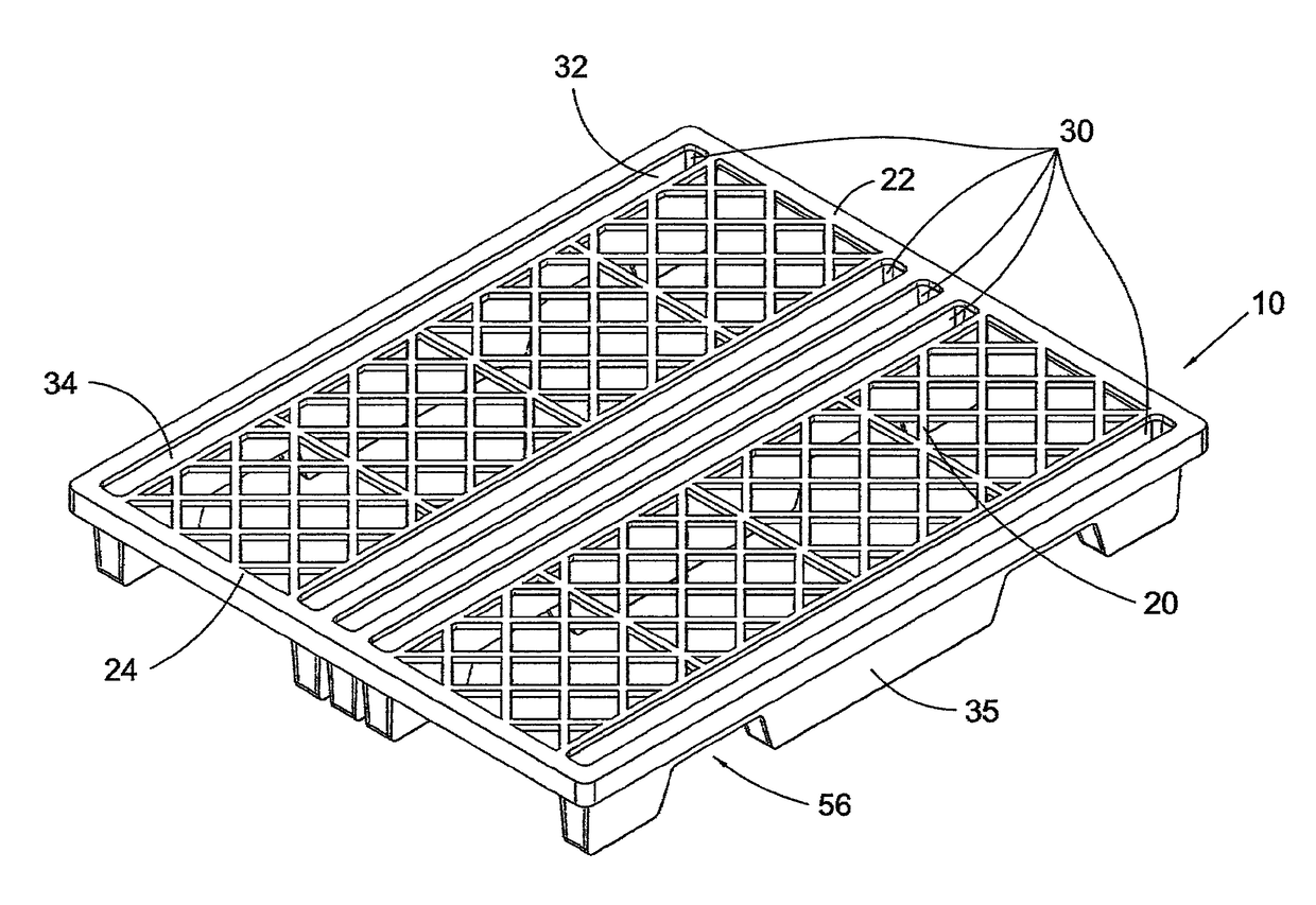
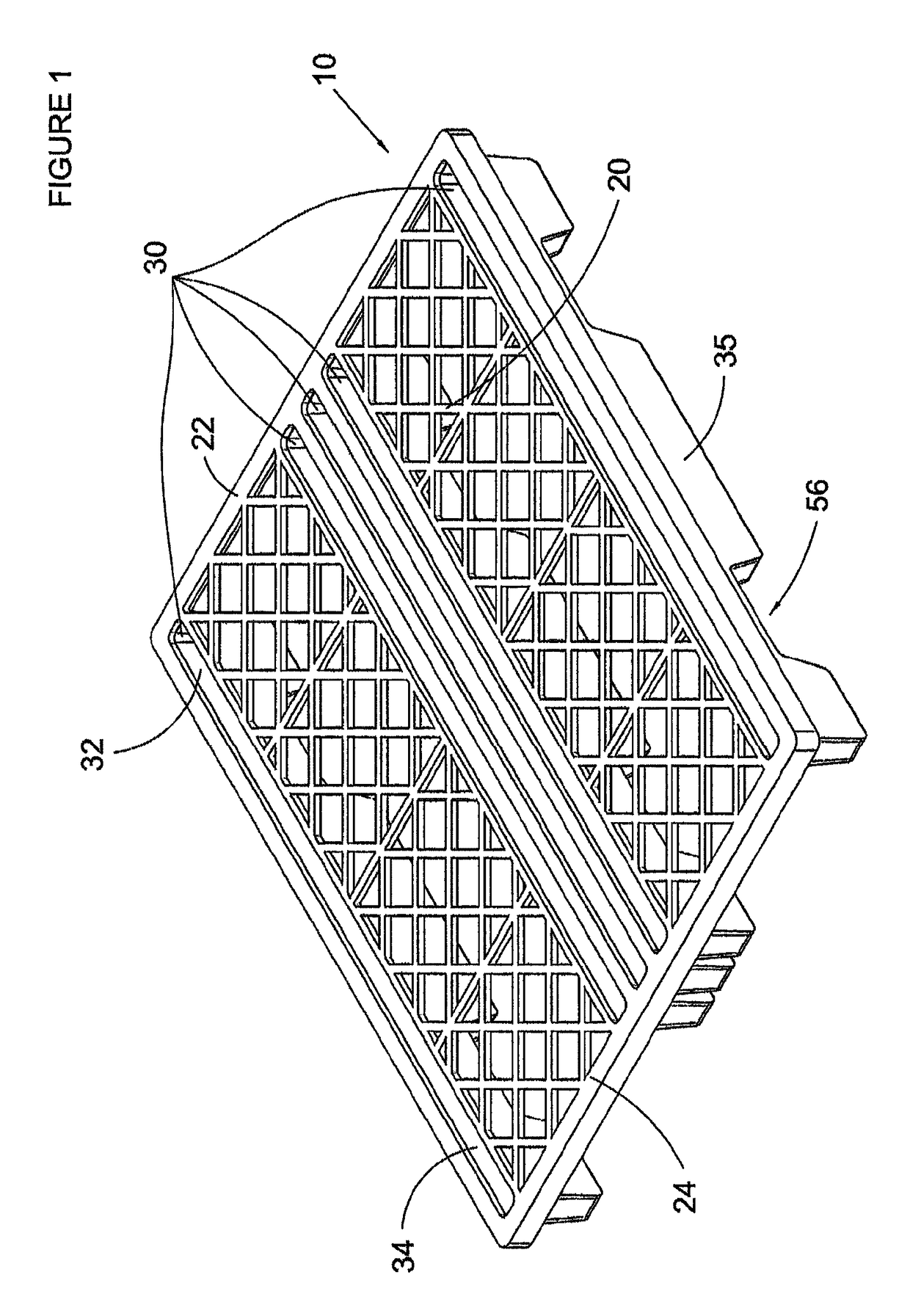
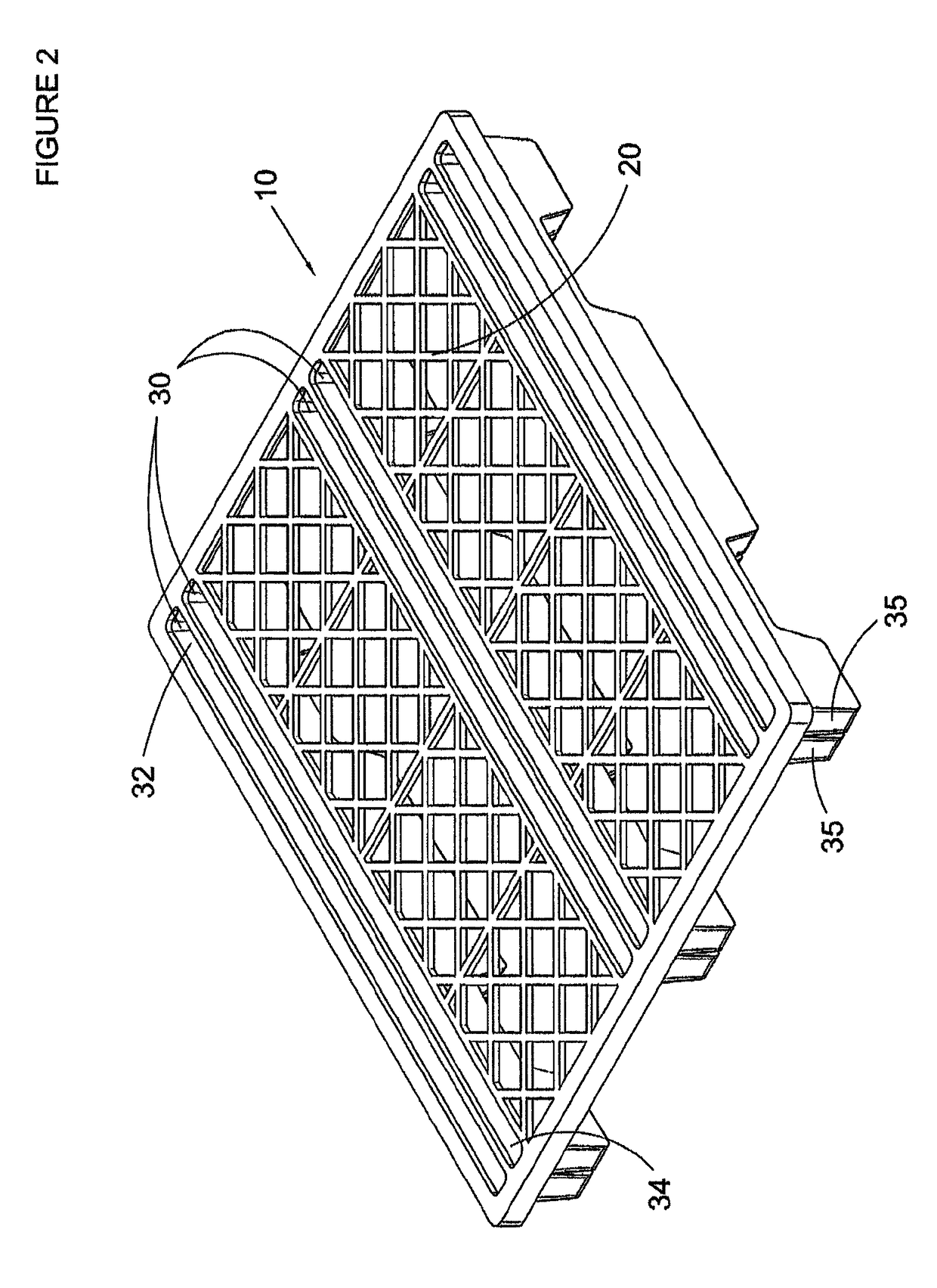
[0053]While not wishing to be limited to the following characteristics, one exemplary embodiment comprises a pallet made by a molding process which may be one of several types including but not limited to structural foam molding and injection molding using thermo plastic polymers, said pallet having overall dimensions of between about 48″ to about 36″ length, about 48″ to 36″ width, and a runner depth (from deck to V / U / flattened V bottom) of between about 2.5″ and about 8″. The runner opening into the deck is preferably between about 1″ to 4″ wide but may be wider or narrower depending on the desired load capacity of the pallet and the specific runner system design. It is possible to mold the pallet of single layer construction, or to employ rotational molding and create a pallet that is double-walled construction and / or hollow at least in part. The thickness of material can be selected to provide strength as needed for the pallet's intended use.

[0054]The pallet of the present inven...


PUM


Abstract

A pallet having a unique runner system where each runner opens into the upper deck of the pallet or opens away from the upper deck, and each runner is formed of a construction of z girts back to back resulting in a flattened “V” or “U”. Each runner may optionally include an elongated notch on its bottom surface or an opening to allow forklift tines to slide into for easy transport of the pallet. The pallet may also include cross runners of similar construction for additional strength. The pallet's construction allows the pallet to be made of plastic material, perhaps molded, providing lighter weight and longer durability than its wooden cousins.

Description

PRIORITY STATEMENT[0001]This application a nonprovisional application based off provisional application No. 61 / 865,012, which was filed on Aug. 12, 2013 with the U.S. Patent and Trademark Office, the entire contents of which is incorporated herein.BACKGROUND[0002]The transport of objects from one place to another has been a challenge since ancient times. Storage of multiple objects also poses challenges. In addition to specialized buildings, shelves, and cupboards for storage and bucket loaders, fork lifts, trucks, carts, planes and ships for transport, pallets have been created.[0003]Pallets can be thought of as a form of a moveable shelf or platform. Depending on the load to be moved, the construction of a pallet is critical to durability and performance. Further, it is desirable that a pallet be constructed such that a loaded pallet may be placed directly on the load of a pallet below without damaging the lower load. Some storage systems employ open racking of pallets which syste...

Claims


Application Information

Patent Timeline
Patent Type & Authority Patents(United States)
IPC IPC(8): B65D19/00
CPCB65D19/0038B65D2519/00034B65D2519/00069B65D2519/0094B65D2519/00955B65D2519/00288B65D2519/00308B65D2519/00318B65D2519/00338B65D2519/00268
Inventor BURK, RYAN
Owner BURK RYAN
Why Eureka
Try Eureka