
Face image capturing device and driver condition determination device

a technology of driver condition detection and image capture, which is applied in the direction of printers, cameras, instruments, etc., can solve the problems of reducing the accuracy of driver condition detection, and achieve the effects of reducing the blurring of normalized face image, small face image, and increasing the blurring of captured face imag

Active Publication Date: 2018-07-10
DENSO CORP
View PDF21 Cites 1 Cited by
  • Summary
  • Abstract
  • Description
  • Claims
  • Application Information

AI Technical Summary

Benefits of technology

[0009]The present disclosure has been made based on the above-described findings of the inventors. An object of the present disclosure is to provide a technology that makes it possible to accurately detect the driver condition even when a fixed-focus in-vehicle camera is used.
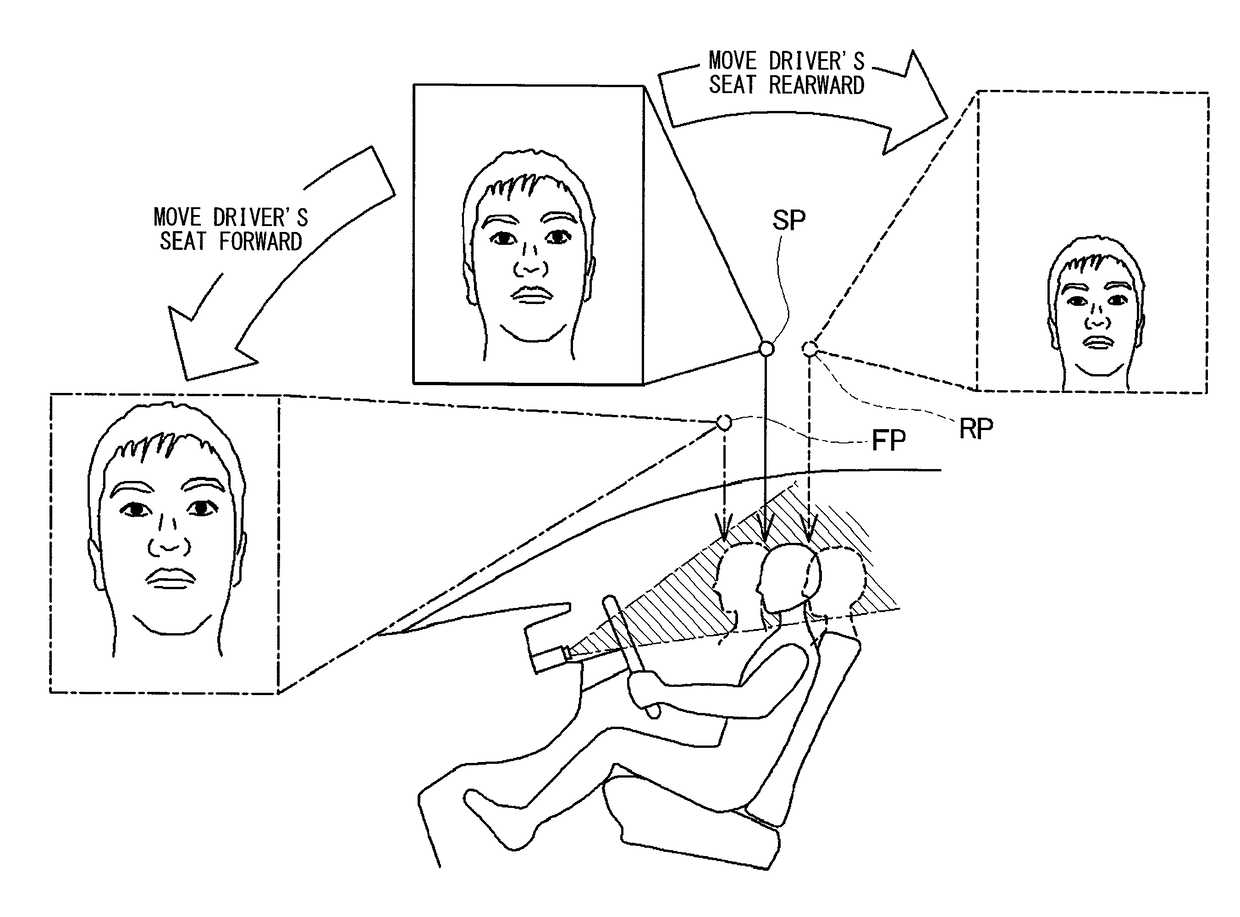
[0021]When the driver's seat is moved rearward by the driver, a relatively small face image is captured. Therefore, the captured face image is enlarged by normalization. When the captured face image is enlarged, the blurring of the captured face image increases. The face image capturing device according to the sixth aspect is capable of capturing a non-blurry face image even when the driver's seat is moved rearward by the driver. Therefore, the blurring of the normalized face image can be reduced. Further, when the driver's seat is moved forward by the driver, a relatively large face image is captured. Therefore, the captured face image is reduced in size by normalization. In this instance, the blurring of the face image is also reduced. Consequently, the blurring of the normalized face image can be reduced without regard to a position to which the driver's seat is moved by the driver. As a result, the driver condition can be accurately determined at all times.

Problems solved by technology

However, when the fixed-focus in-vehicle camera is used, the accuracy of driver condition detection may decrease even if the optical aperture is optimally set to obtain a sharp face image within the whole range of face position movement of the driver.

Method used


Image

  • Face image capturing device and driver condition determination device
  • Face image capturing device and driver condition determination device
  • Face image capturing device and driver condition determination device

Examples


Embodiment Construction

[0037]An embodiment of the present disclosure will now be described to clearly define the above-described present disclosure.

A. Device Configuration

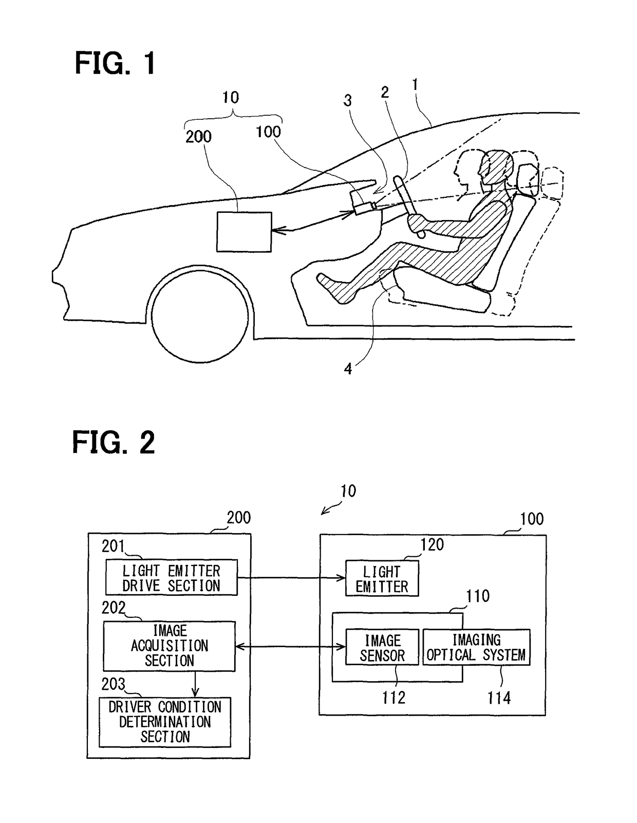
[0038]FIG. 1 illustrates a vehicle 1 in which a driver condition determination device 10 according to the embodiment is mounted. The driver condition determination device 10 includes an image capturing unit 100 and a control device 200. The image capturing unit 100 is disposed in front of a driver. The control device 200 is connected to the image capturing unit 100. The image capturing unit 100 is disposed in front of an instrument panel that is positioned behind a steering wheel 2 as viewed from the driver, and capable of capturing a face image of the driver. In FIG. 1, the driver is shaded with hatching for purposes of illustration.

[0039]The seat position of a driver's seat 4 in which the driver is seated can be adjusted in a front-rear direction. Adjusting the seat position moves the face position of the driver forward or rearward. In...


PUM


Abstract

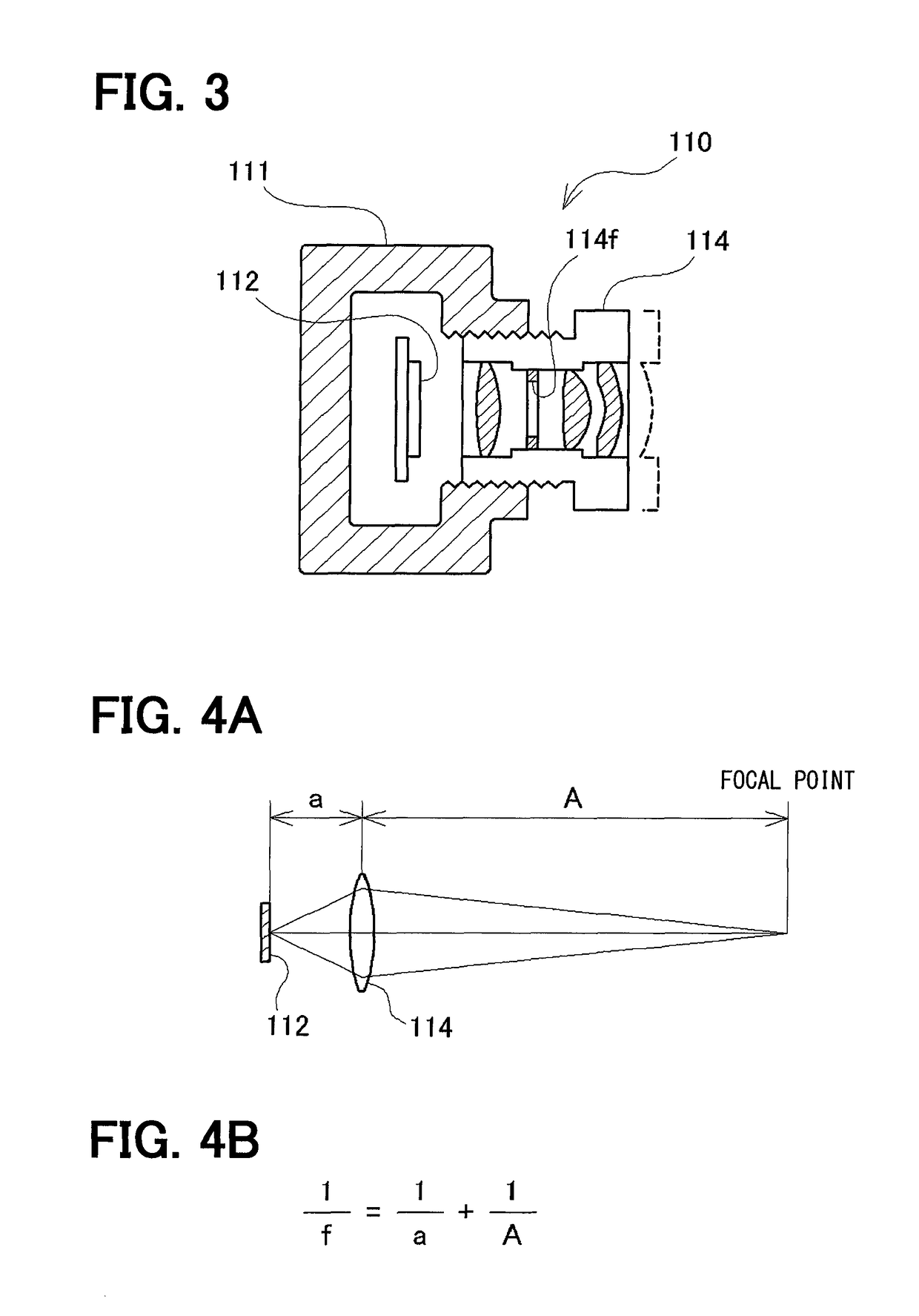
In a face image capturing device, a focal point of a fixed-focus in-vehicle camera is set to a position where a circle of confusion with respect to a foremost face position is larger than the circle of confusion with respect to a rearmost face position. The rearmost face position is where the driver's face is positioned when a driver's seat is moved to the rearmost limit. The foremost face position is where the driver's face is positioned when the driver's seat is moved to the foremost limit. When the focal point of the in-vehicle camera is set to the above position, the focal point can be moved rearward to reduce the blurring of a face image at the rearmost face position. Even if the blurring of the face image at the rearmost face position is increased, a driver condition can be accurately determined at all times.

Description

CROSS REFERENCE TO RELATED APPLICATION[0001]This application is based on Japanese Patent Application No. 2013-261880 filed on Dec. 18, 2013, the disclosure of which is incorporated herein by reference.TECHNICAL FIELD[0002]The present disclosure relates to a face image capturing device that captures an image of the face of a driver by using an in-vehicle camera, and also relates to a driver condition determination device that analyzes the face image to determine the condition of the driver.BACKGROUND ART[0003]A well-known driving assistance technology analyzes a driver's face image captured by an in-vehicle camera to determine the condition of a driver that affects driving safety, such as the awareness, aimlessness, and drowsiness of the driver during driving (the condition of the driver is referred to as the “driver condition” in this description), and issues, for example, a warning as needed. For accurate determination of the driver condition, it is preferred that the driving assis...

Claims


Application Information

Patent Timeline
Patent Type & Authority Patents(United States)
IPC IPC(8): G06K9/00G03B3/02G08B21/06H04N5/232G03B15/00G06K9/32G06K9/42G06V10/32
CPCG06K9/00845G03B3/02G06K9/00255G08B21/06H04N5/23219H04N5/23296H04N5/23229G06K9/42G03B15/00G06K9/00281G06K9/3241G06V40/166G06V40/171G06V20/597G06V10/255G06V10/32H04N23/611H04N23/80H04N23/69
Inventor OMI, TAKUHIRO
Owner DENSO CORP
Learn More