
Control device for hybrid vehicle and hybrid vehicle

a control device and hybrid technology, applied in the direction of engine-driven generator propulsion, external condition input parameters, transportation and packaging, etc., can solve the problems of degrading the durability of the brake, so-called reverse travel between the two motors cannot be performed, etc., and achieve the effect of suppressing the degradation of the durability of the selectable one-way clutch or the lik

Active Publication Date: 2018-07-24
TOYOTA JIDOSHA KK
View PDF15 Cites 0 Cited by
  • Summary
  • Abstract
  • Description
  • Claims
  • Application Information

AI Technical Summary

Benefits of technology

[0008]An object of the present invention is to increase driving torque during a reverse travel while avoiding or inhibiting excessive torque from acting on an engagement mechanism or a member whose rotation is stopped by the engagement mechanism, the engagement mechanism stopping rotation of an engine, a rotational member that is coupled to the engine, or an engine shaft during the forward travel of the vehicle in a hybrid vehicle that can travel by a motor.
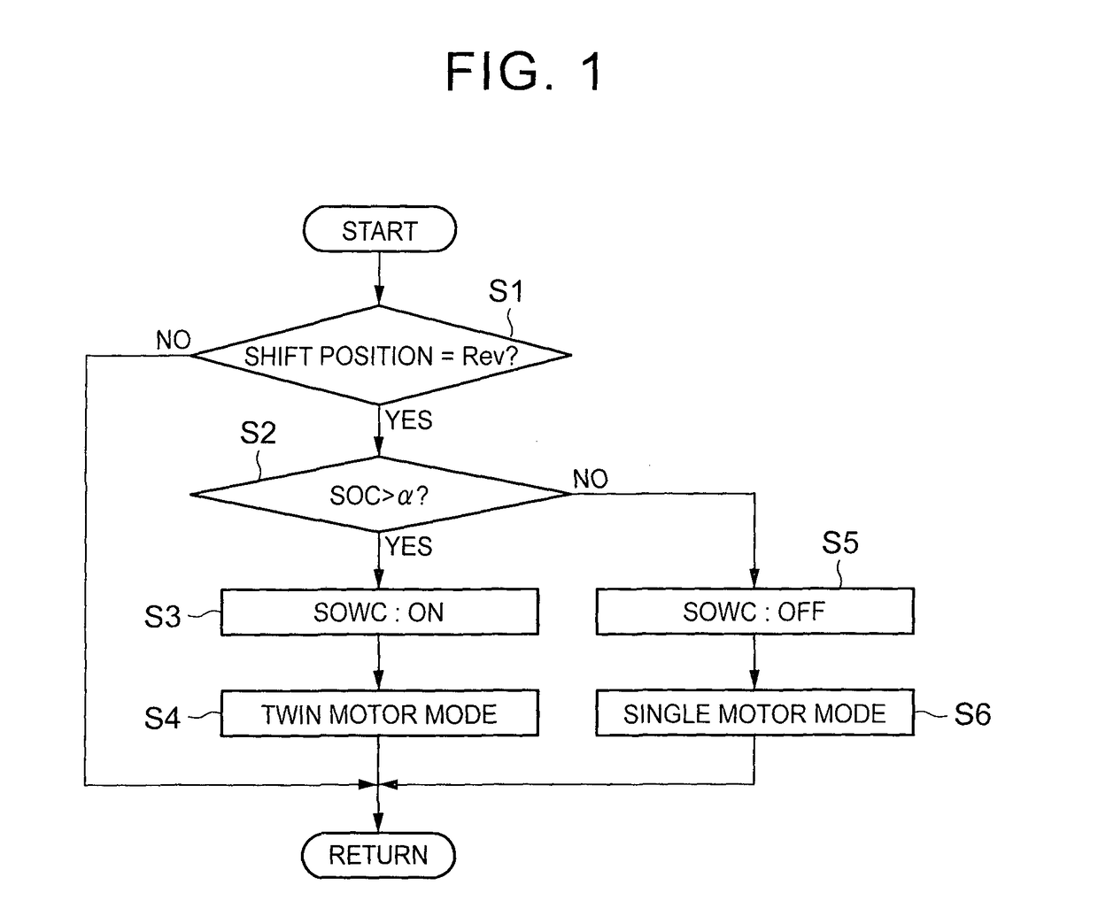
[0010]According to the above aspect, the second motor operates as a drive power source for a reverse travel. In this case, since the engagement mechanism stops the rotation of the output shaft of the engine or the rotational member that is coupled thereto, the torque that is output by the first motor can serve as drive torque for the reverse travel. As a result, the two motors can operate as the drive power sources for the reverse travel, and thus the large drive power can be obtained. In addition, the engagement mechanism is disengaged and the output shaft of the engine or the rotational member that is coupled thereto can rotate in the case of a forward travel. Accordingly, it is possible to prevent or suppress torque that acts on the engagement mechanism or the rotational member whose rotation is stopped thereby from becoming excessive when so-called reverse input from a drive wheel side becomes large due to resonance or the like that is caused by abrupt braking or repeated change in traveling resistance.
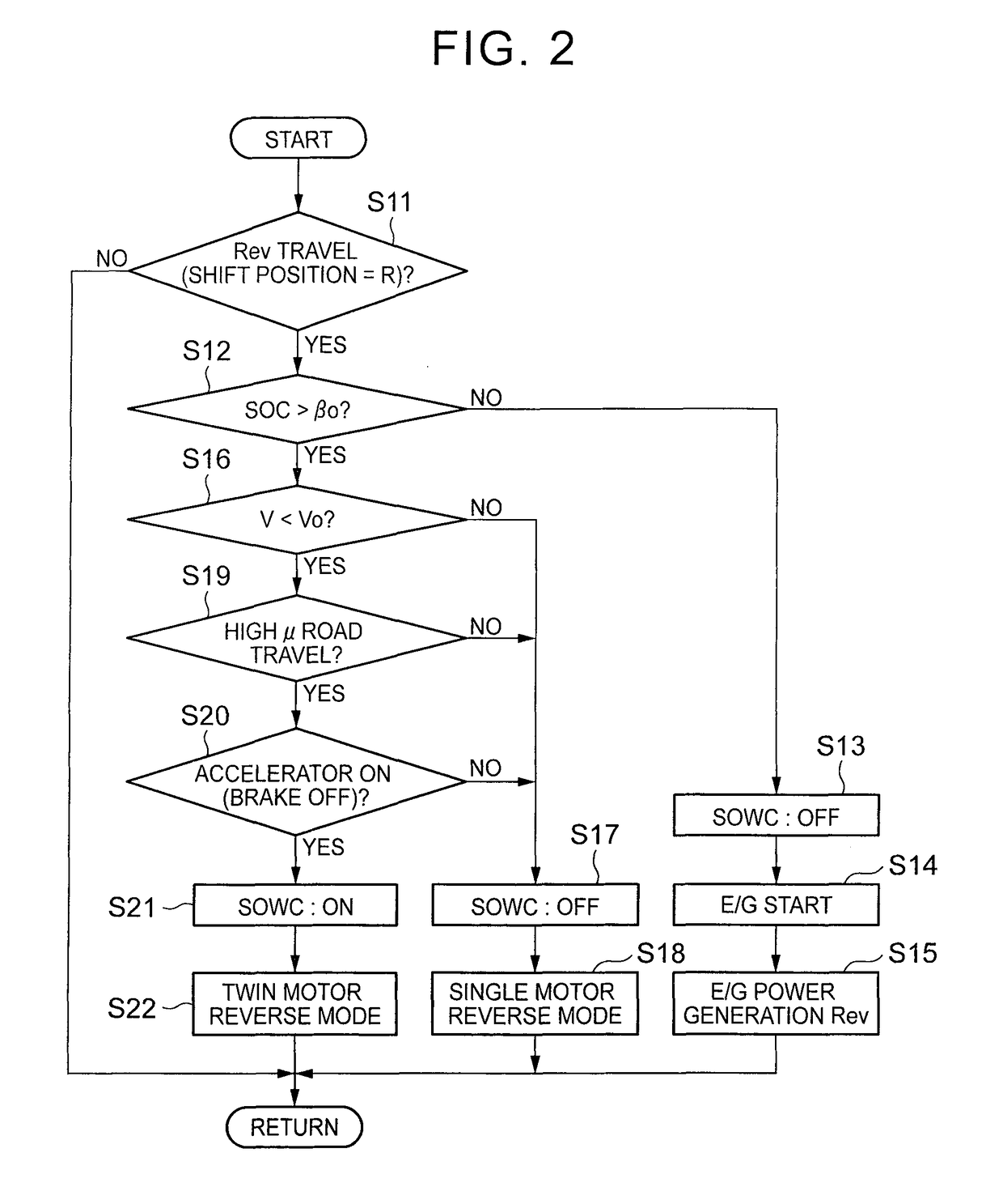
[0013]According to the above aspect, a state in which the parking brake mechanism is engaged and the vehicle is parked is switched to the reverse travel state on the downhill. In this case, since the parking brake mechanism is switched to the disengaged state, a load that acts on the parking brake mechanism due to gravitational acceleration is canceled, and in conjunction with this, the vehicle moves for a distance that corresponds to backlash that exists inevitably in a power transmission mechanism. Then, the engagement mechanism is switched to the engaged state. Thus, it is possible to prevent or suppress temporary torque that is generated in conjunction with the disengagement of the parking brake mechanism from acting on the engagement mechanism or the rotational member whose rotation is stopped thereby.
[0015]According to the above aspect, when the engagement mechanism is engaged and the vehicle travels reversely, and when it is predicted that large torque acts on the engagement mechanism or the rotational member whose rotation is stopped by the engagement mechanism, the engagement mechanism is disengaged, and the rotation of the rotational member is allowed. Accordingly, when the large torque acts, the rotational member rotates and receives the torque. Thus, the excessive torque is avoided from acting on the engagement mechanism or the rotational member.
[0017]According to the above aspect, if it is configured that the engagement mechanism is engaged and the drive power is generated by both of the first and second motors only in the case where the high drive power is requested in the reverse travel state, such as in the case of an uphill road or in the case where the vehicle runs over a step, an opportunity that the engagement mechanism is engaged is limited. Thus, it is possible to suppress the excessive torque from acting on the engagement mechanism or the member whose rotation is stopped thereby.
[0020]According to the above aspect, the engagement mechanism is constructed from the selectable one-way clutch. Accordingly, the vehicle can travel reversely by only using the second motor in a state that the engagement mechanism remains to be engaged and that an operation state thereof is not switched during the reverse travel. In this case, if the selectable one-way clutch is switched to a disengaged state, so-called dragging of the selectable one-way clutch can be resolved. Furthermore, the selectable one-way clutch not only maintains the engaged state in a uniform manner when torque in a specified direction acts thereon but also can be switched to the disengaged state that rotation in the specified direction is allowed when the torque in the specified direction acts thereon. Thus, the selectable one-way clutch is controlled in the disengaged state as necessary, such as when the excessive torque is predicted. Therefore, degradation of durability of the selectable one-way clutch or the like can be suppressed.

Problems solved by technology

Therefore, in the above configuration, so-called reverse travel by the two motors cannot be performed.
This can cause degraded durability of the brake.

Method used


Image

  • Control device for hybrid vehicle and hybrid vehicle
  • Control device for hybrid vehicle and hybrid vehicle
  • Control device for hybrid vehicle and hybrid vehicle

Examples


Embodiment Construction

[0030]The present invention is a control device for a hybrid vehicle, and the hybrid vehicle includes an internal combustion engine (an engine) and a motor having a power generation function as drive power sources. The present invention particularly includes at least two motors. The hybrid vehicle is a so-called two motor type in which a first motor and the engine are coupled to a power split mechanism that includes a differential mechanism, in which power generated by the first motor that functions as a power generator is supplied to a second motor, and in which power is output from the second motor to an output member. An example of such a hybrid vehicle is schematically shown in FIG. 6.

[0031]An engine (ENG) 1 and a first motor generator (MG1) 2 are coupled to a power split mechanism 3. The first motor generator (MG1) 2 is an example of the first motor of the present invention. This power split mechanism 3 is configured to perform a differential action by using three rotational el...


PUM


Abstract

A hybrid vehicle includes: an engine; a first motor; an output member; a differential mechanism, the engine, the first motor, and the output member being coupled via the differential mechanism; a second motor configured to apply torque to the output member; and an engagement mechanism configured to stop rotation of an output shaft of the engine or rotation of a specified rotational member that is coupled to the output shaft of the engine. An electronic control unit is configured to (i) engage the engagement mechanism when the hybrid vehicle travels reversely by drive power of the second motor or drive power of the first motor and the second motor, and (ii) disengage the engagement mechanism when the hybrid vehicle travels forward by the drive power of the second motor or the drive power of the first motor and the second motor.

Description

BACKGROUND OF THE INVENTION[0001]1. Field of the Invention[0002]The present invention relates to a device that controls a hybrid vehicle including an engine and a motor as drive power sources and a hybrid vehicle. The present invention particularly relates to a control device for a hybrid vehicle that is configured such that an engine and a first motor having a power generation function are coupled to a power split mechanism having a differential function and that power generated by the first motor is supplied to a second motor that generates drive power for traveling and to a hybrid vehicle.[0003]2. Description of Related Art[0004]Examples of a hybrid vehicle of this type are described in Japanese Patent Application Publication No. 8-295140 (JP 8-295140 A) and Japanese Patent Application Publication No. 2013-141959 (JP 2013-141959 A). A configuration of such a hybrid vehicle will be described briefly. A planetary gear mechanism of single pinion type is provided as a power split mec...

Claims


Application Information

Patent Timeline
Patent Type & Authority Patents(United States)
IPC IPC(8): B60K6/26B60W20/00B60W30/18B60K6/383B60K6/445B60W10/02B60W10/08B60W20/40B60K6/387B60W30/184B60K6/38B60L50/16
CPCB60W20/40B60K6/383B60K6/387B60K6/445B60W10/02B60W10/08B60W20/00B60W30/18036B60K6/26Y10S903/913B60K2006/381B60W30/1846B60W2510/244B60W2520/10B60W2550/148B60W2710/027B60W2710/08B60W2720/24B60Y2200/92B60Y2300/18033Y02T10/6239Y02T10/7258Y10S903/906B60W2552/40Y02T10/62Y02T10/72B60W10/06B60W10/12
Inventor KOMADA, HIDEAKISHIBATA, HIROYUKIKUROSAKI, YUKISHIOIRI, HIROYUKI
Owner TOYOTA JIDOSHA KK
Learn More