
Roll stability control using four-wheel drive

a stability control and four-wheel drive technology, applied in the direction of machine control, instrumentation, process control, etc., can solve the problems of affecting the performance of vehicle roll and yaw stability control, affecting the stability of the vehicle, and prone to oversteering the vehicle, so as to improve the driving torque of the driven wheels, reduce the tendency of vehicle rollover, and simple driving torque control

Active Publication Date: 2006-04-06
FORD GLOBAL TECH LLC
View PDF99 Cites 91 Cited by
  • Summary
  • Abstract
  • Description
  • Claims
  • Application Information

AI Technical Summary

Benefits of technology

[0010] In the present invention, the drive torques may be increased in both front and rear axles using the 4×4 system. Thus, due to the friction circles at the tires, the tire lateral forces in the front and the rear wheels, especially in outside wheels, can be altered accordingly. One advantage of the present invention is that roll stability control performances can be achieved not only by the front outside wheel but also by the rear outside wheel. While in brake-based roll stability control, braking the front outside wheel is the main control mechanism. The weight transfer due to acceleration through driving torque management in a 4×4 system may be more favorable for roll stability control purposes than the weight transfer due to deceleration during braking from a brake control system. The acceleration causes the vehicle weight transfer from the front to the rear, while the deceleration causes the vehicle weight transfer from the rear to the front. Hence, the rear wheel might have a higher level of tire forces in four-wheel drive mode. That is, the rear lateral tire forces are more useful for roll stability control than those generated in the rear axle during a braking event. At the same time, the front tires have a lower level of tire forces than in the braking case. Hence, both front and rear tires are effective in terms of removing lateral forces through increasing longitudinal tire forces. The reduced tire lateral forces lead to reduced vehicle lateral acceleration applied to the center of gravity of the vehicle body. Therefore, the overturning roll moment of the vehicle generated from the force couple of tire lateral forces and the vehicle centripetal force applied to the center of gravity of the vehicle body will be reduced.
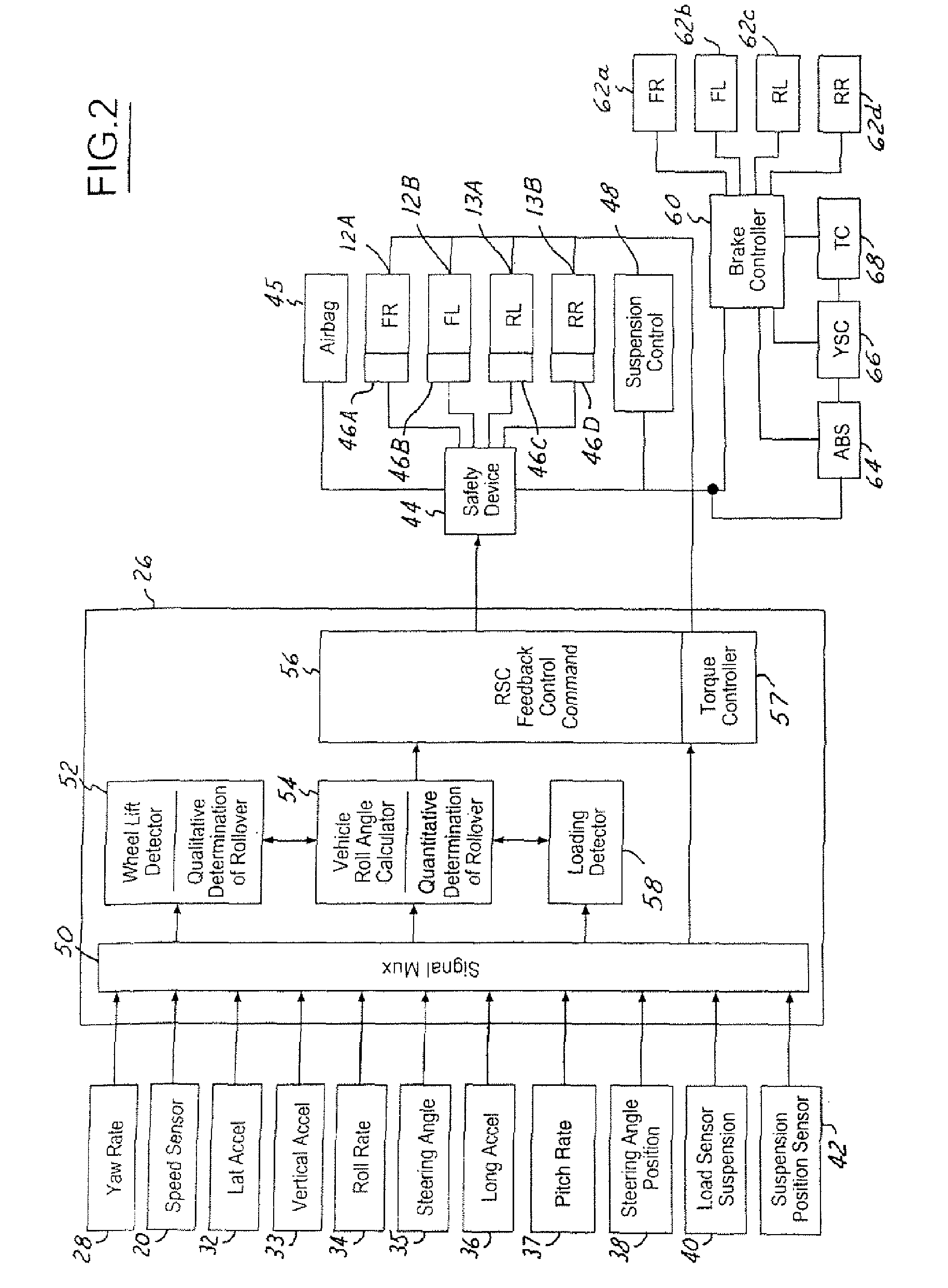
[0011] Although the vehicle rollover trend might be reduced by applying throttle in the engine controls so as to increase driving torque of the driven wheels, the longitudinal force offsets between the outside wheels and inside wheels (due to vehicle weight transferred from inside wheels to outside wheels) may generate a moment which tends to over-steer the vehicle. The larger the vehicle chassis or suspension roll angle the larger the longitudinal force offset between the inside and outside wheels. Therefore, a simple driving torque control could reduce the roll trending but at the expense of inducing some vehicle over-steer. Since an increased over-steer could eventually reduce the benefit of tire lateral force reduction, and over-steer during an increased vehicle speed might cause yaw stability problems, a simple driving torque scheme alone might be inappropriate for achieving vehicle roll and yaw stability control performances. In order to eliminate such an adverse effect, an integration between the driving torque control and the brake torque control through controlling the corresponding ECUs is pursued. For this reason, a desirable roll stability control using a 4×4 system might include control units of a brake control system, an engine control system and a 4×4 system control.
[0012] In one aspect of the invention, a method of controlling a vehicle equipped with a 4×4 system comprises determining a potential rollover condition and transferring driving torque to the front wheels and coordinating the driving torque at one wheel location with braking torque at another location to prevent a potential on-road rollover from happening, or if there are both driving and braking torque requested at the same wheel location, resolving the conflict through prioritizing and arbitrating.
[0013] In a further aspect of the invention, a method of controlling a vehicle equipped with a 4×4 system comprises generating a rollover signal in response to the potential rollover, increasing the torque in the front wheel through the active differential or in a slip-limit differential case through the combination of increasing torque and increasing braking torque in response to the rollover signal, and braking a rear outside wheel in response to the rollover signal.
[0014] In yet another aspect of the invention, a method of controlling a vehicle having an active center differential included in a transfer case and active axle differentials comprises determining a rollover condition, in response to the rollover condition, disengaging an inside wheel from an outside wheel with an active axle differential and thereafter, determining a wheel lift condition of the inside wheel.
[0015] In yet another aspect of the invention, a method for controlling the vehicle rollover having an active center differential and active axle differentials comprise determining a rollover condition, in response to the rollover condition, disengaging an outside front wheel from an inside wheel with the active axle differential, applying a brake torque to the outside front wheel and applying driving torque to an outside rear wheel to counter the deceleration caused by braking the front outside wheel.

Problems solved by technology

Although the vehicle rollover trend might be reduced by applying throttle in the engine controls so as to increase driving torque of the driven wheels, the longitudinal force offsets between the outside wheels and inside wheels (due to vehicle weight transferred from inside wheels to outside wheels) may generate a moment which tends to over-steer the vehicle.
Since an increased over-steer could eventually reduce the benefit of tire lateral force reduction, and over-steer during an increased vehicle speed might cause yaw stability problems, a simple driving torque scheme alone might be inappropriate for achieving vehicle roll and yaw stability control performances.

Method used


Image

  • Roll stability control using four-wheel drive
  • Roll stability control using four-wheel drive
  • Roll stability control using four-wheel drive

Examples


Embodiment Construction

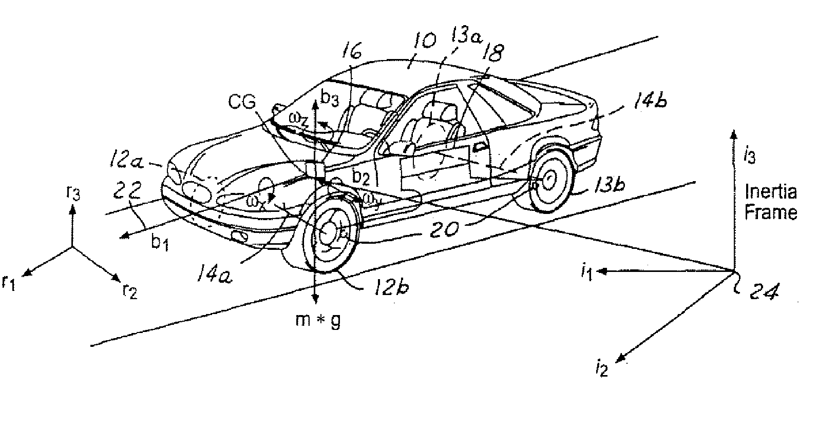
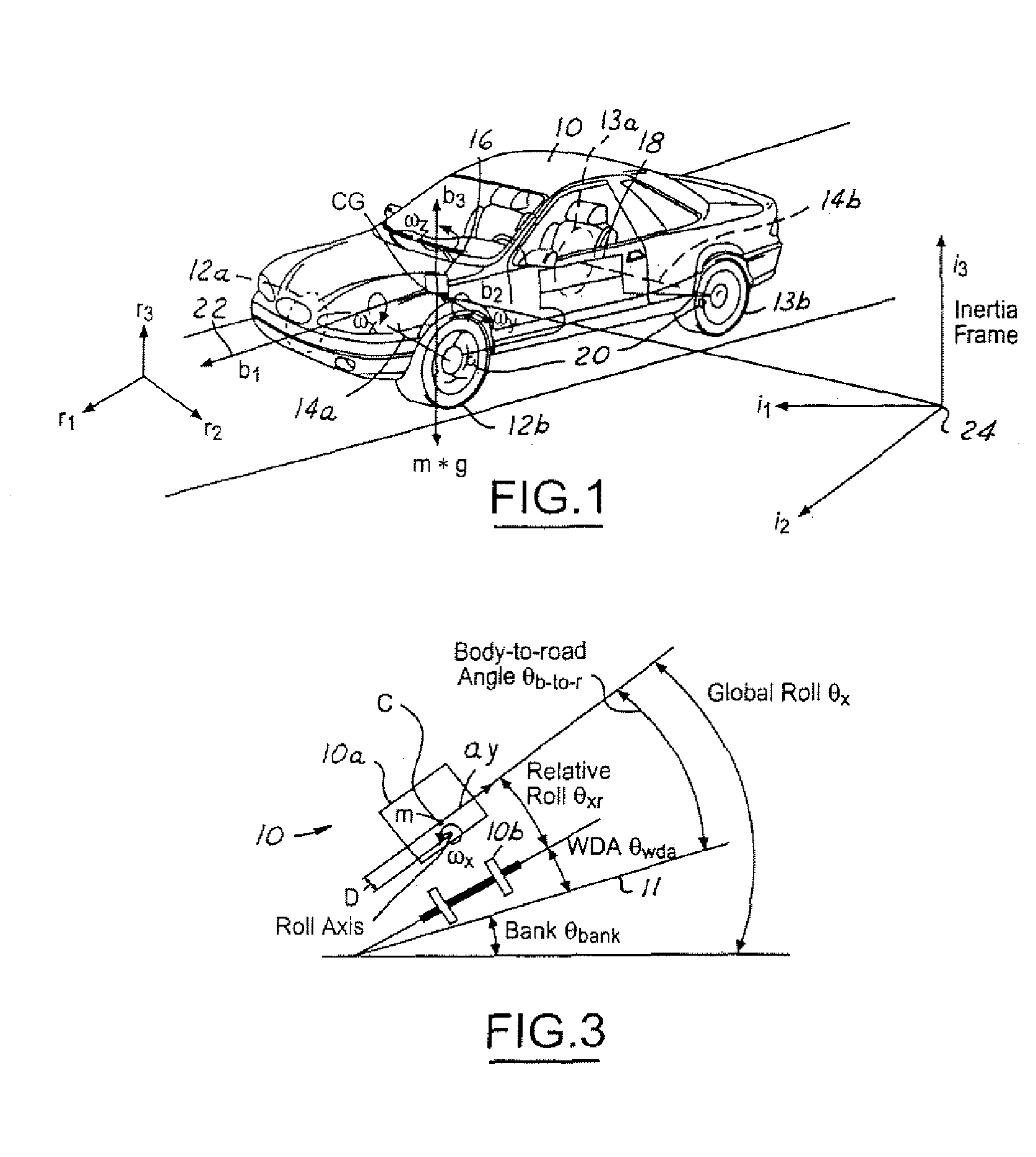
[0029] In the following figures, the same reference numerals will be used to identify the same components. The present invention is preferably used in conjunction with a roll stability control system or a rollover stability control or a rollover control system for a vehicle. However, the present invention may also be used with a deployment device such as an airbag or an active roll bar. The present invention will be discussed below in terms of preferred embodiments relating to an automotive vehicle moving in a three-dimensional road terrain. Also, the system may be used with a four-wheel drive or all-wheel drive vehicle. Such a vehicle is generally referred to as a four driven wheel vehicle since each of the wheels is capable of generating longitudinal forces derived from the powertrain.

[0030] Referring to FIG. 1, an automotive vehicle 10 with an active safety system of the present invention is illustrated with the various forces and moments thereon during a potential rollover cond...


PUM


Abstract

A control system (18) and method for controlling an automotive vehicle (10) includes a number of sensors that are used to generate a potential rollover signal. In response to the potential rollover, active differentials (112, 114, 116) may be used alone or in addition to braking to prevent the vehicle from rolling over.

Description

TECHNICAL FIELD [0001] The present invention relates generally to a roll stability control system in a vehicle and, more specifically to a roll stability control system for an all-wheel drive vehicle or a four-wheel drive (partial time all wheel drive) vehicle. BACKGROUND [0002] Traditionally, vehicles have a 4×2 system where only two wheels at one axle (either the front or the rear) can provide driving torques. Recently, many SUVs have a 4×4 system which can distribute power to all four wheels instead of two wheels. The benefit of the 4×4 system is easy to understand. Such a system has the potential to double the amount of longitudinal force over a conventional 4×2 system if the traction potentials of the tires exceed the driving torques applied. There are three types of 4×4 systems, namely, the part-time 4×4 system, the all wheel drive system (AWD) and the torque-on-demand (TOD) System. [0003] In the part-time 4×4 system, the driver is allowed to select a four-wheel drive (4WD) mo...

Claims


Application Information

Patent Timeline
Patent Type & Authority Applications(United States)
IPC IPC(8): G05D1/00B60K23/04B60K23/08B60W10/00B60W10/06B60W30/04
CPCB60G17/016B60G2800/0124B60G2800/0194B60G2800/213B60K23/04B60K23/0808B60T2201/14B60W10/06B60W10/119B60W10/16B60W10/184B60W30/04B60W40/072B60W40/076B60W2550/142B60W2720/18B60W2552/15B60K17/346B60K28/14F16H48/20
Inventor MEYERS, JOELU, JIANBOBREWER, MICHAELMATTSON, KEITHBROWN, TODD
Owner FORD GLOBAL TECH LLC
Learn More