Flexible liquid transport tank with surge dampening baffles

a technology of liquid transport tank and baffle, which is applied in the direction of container, item transportation vehicle, box, etc., can solve the problems of surge of liquid, affecting the balance and control of aircraft or vehicles, and introducing significant complexity and cost to the manufacture of flexible tanks, so as to reduce contamination and fuel loss, eliminate wasted flights, and save money

Active Publication Date: 2018-07-24
DONMARK HLDG
View PDF6 Cites 1 Cited by
  • Summary
  • Abstract
  • Description
  • Claims
  • Application Information

AI Technical Summary

Benefits of technology

[0014]The present invention provides a flexible fuel (or other liquid) transport tank that enables cargo aircraft, both civilian and military, to support remote site fuel cache operations. Each tank may be customized and fitted to specific fixed wing or rotary wing aircraft to maximize the lifting capabilities of the air craft and to ensure the correct centre of gravity and liquid surge dampening system is applied.
[0017]The flexible liquid transport tanks of the present invention effectively convert any aircraft into a flying tanker, enabling bulk fuel to be delivered to remote sites. When a flexible liquid transport tank is empty, it can be rolled up and stored, thereby releasing the space in the aircraft for other cargo or passengers.
[0018]One of the benefits provided by the present invention is that it eliminates wasted flights where only empty fuel drums or hard tanks are being removed from remote sites; the return flights can be used to carry other payloads. This not only saves money, but is a more environmentally sound practice since many empty conventional fuel drums are usually simply abandoned at the remote sites. The present invention also enables virtually any aircraft to be quickly converted into or from a bulk fuel tanker, thereby allowing for dual use operations. The present invention further reduces contamination and fuel loss from minor spills that are often associated with fuel drums, and it reduces the overall environmental footprint of a remote site fueling operation.
[0019]The flexible liquid transport tank of the present invention is designed to minimize liquid dynamics and any effects to the centre of gravity of the aircraft. The tank has a new and unique fabric and cable baffling system that limits the liquid dynamic of the fuel during flight. This new cable baffling system enables the manufacturer to custom size each tank to specific aircraft.

Problems solved by technology

However, while they provide an efficient means of transporting large volumes of liquid, these kinds of flexible tanks have an inherent tendency to allow the free flow of liquid within them which can lead to liquid surges as a result of the acceleration and deceleration of the liquid.
It has long been recognized that free flowing liquids can be dangerous to the balance and control of aircraft or vehicles.
The disadvantage of this design is that the pockets or convolutions that attenuate the liquid surges in the tank are usually in a collapsed state when the liquid is at rest in the tank.
While the Headrick baffle systems may operate to attenuate some fluid surges in a flexible fluid tanks, the baffles introduce significant complexity and cost to the manufacture of the flexible tanks in which they are employed, and they also significantly increase the weight and bulk of the flexible tank when empty and thereby affect its collapsibility.
Furthermore, while the Headrick flexible tank and baffle system may operate to attenuate some fluid surges in a flexible fluid tank in the longitudinal direction to the tank, they do very little to attenuate fluid surges in lateral directions.

Method used


Image

  • Flexible liquid transport tank with surge dampening baffles
  • Flexible liquid transport tank with surge dampening baffles
  • Flexible liquid transport tank with surge dampening baffles

Examples


Embodiment Construction

[0031]For the purposes of promoting an understanding of the principles of the invention, reference will now be made to the exemplary embodiments illustrated in the drawings, and specific language will be used to describe the same. It will nevertheless be understood that no limitation of the scope of the invention is thereby intended. Any alterations and further modifications of the inventive features illustrated herein, and any additional applications of the principles of the invention as illustrated herein, which would occur to one skilled in the relevant art and having possession of this disclosure, are to be considered within the scope of the invention.

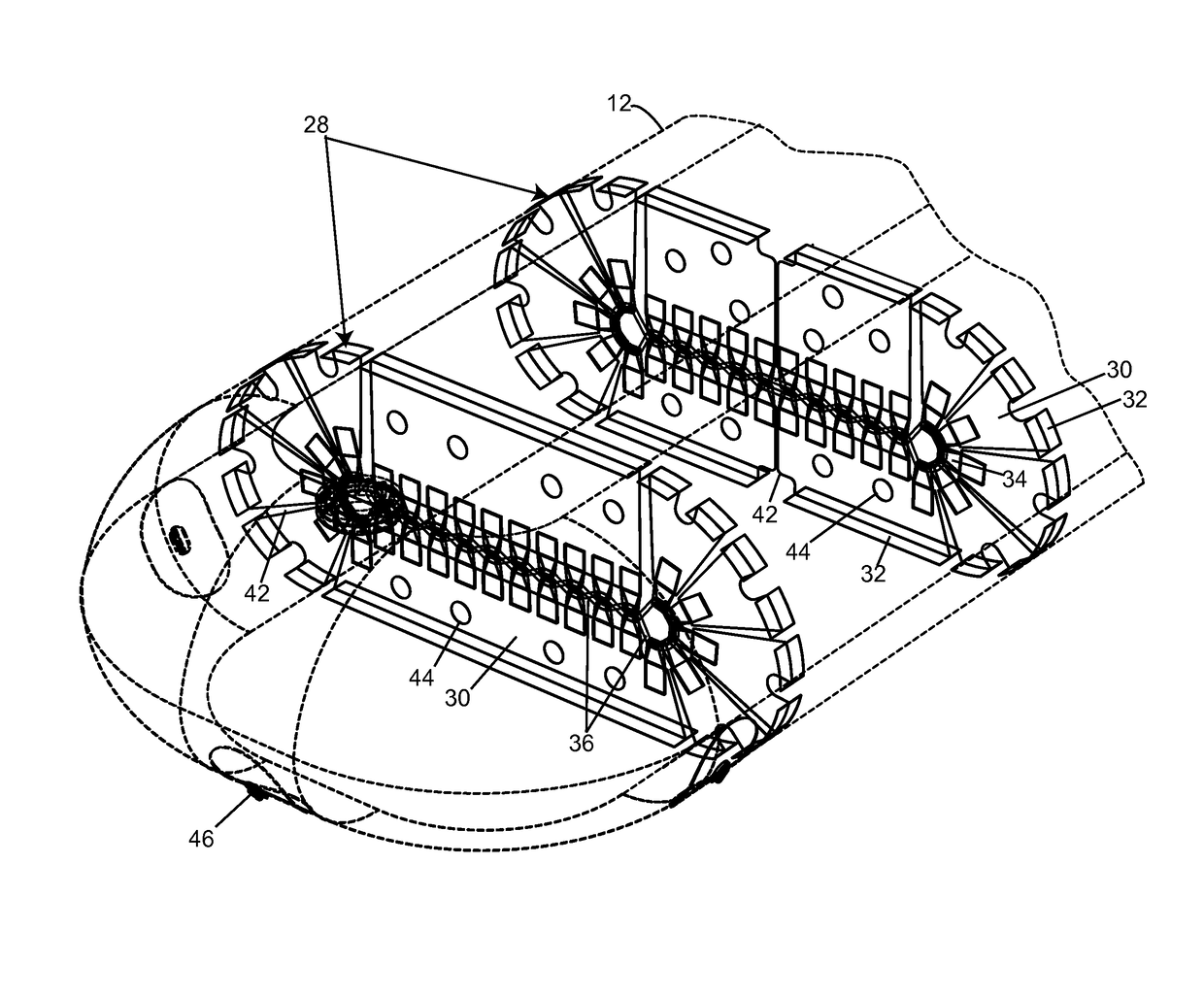
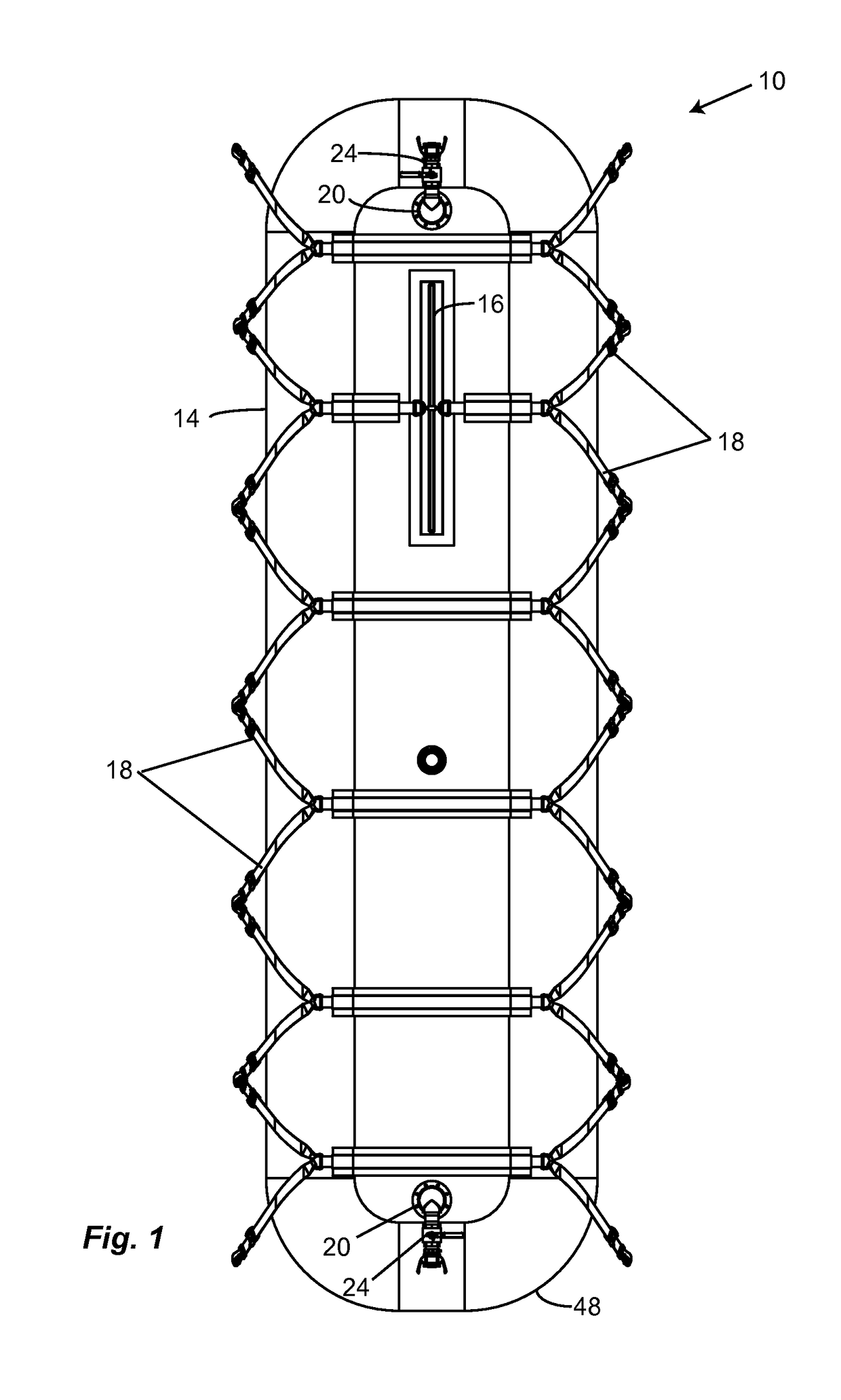
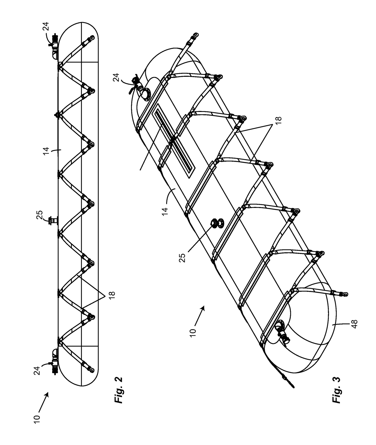
[0032]Referring to FIGS. 1-8, an embodiment of a flexible liquid transport tank in accordance with the present invention is shown generally by reference number 10. The flexible liquid transport tank illustrated is a double layered or “walled” design, comprising of an inner tank 12 that is removably received within an outer tank 14....


PUM


Abstract

Flexible tanks for transporting liquids comprising a flexible bladder to contain liquid, several transverse surge dampening baffles inside the bladder, each baffle comprising several flexible panels, each having a base connected to the inside of the bladder and aligned along a plane transverse to the bladder and an unsupported terminal end opposite the base and adapted to converge with the unsupported portions of adjacent panels in a manner that defines a barrier to fluid flow across the transverse baffle when the bladder is filled; and a connector for interconnecting the terminal ends of the panels. There may be provided a flexible outer bladder of an abrasion resistant material that is adapted to removably receive the inner bladder. There may be provided longitudinal baffles situated between adjacent transverse baffles that define longitudinal compartments with restricted fluid flow there between for dampening lateral fluid surges.

Description

BACKGROUND OF THE INVENTION[0001]1. Field of the Invention[0002]The present invention generally relates to flexible tanks for transporting liquids, and more particularly to flexible transportation tanks of the type comprised of a fluid resistant fabric material which, when filled, may be transported by air carrier to a desired location, and when emptied may be rolled and / or folded into a compact size for return transport and refilling.[0003]2. Description of Related Art[0004]Flexible containers are used for the handling, storage and transportation of large volumes of liquids, such as water or fuel, to remote sites. These containers are commonly referred to as bladder or pillow tanks, and they are typically rectangular so that they can be efficiently loaded onto vehicles for transportation. Examples of some prior art flexible liquid containers are found in U.S. Pat. No. 4,573,508 to Knaus and U.S. Pat. No. 5,499,743 to Blumenkron. Flexible liquid containers, such as exemplified in Kn...

Claims


Application Information

Patent Timeline
Patent Type & Authority Patents(United States)
IPC IPC(8): B65D6/00B65D8/00B65D8/14B65D25/00B65D1/24B64D37/06B64D37/08B65D1/42B65D88/08B65D33/02B65D90/52B65D88/16B65D90/00
CPCB65D88/1606B65D90/52B65D90/004
Inventor YAREMENKO, VICTORLUMSDEN, RICHARDBARTZ, GEORGEREICHARD, PAUL
Owner DONMARK HLDG
Why Eureka
Try Eureka