Air admittance and check valve

a check valve and air technology, applied in the field of air admittance valves, can solve the problems of prolonging the life of the valve, and achieve the effects of reducing friction, and reducing the risk of slipping

Active Publication Date: 2018-07-24
DI MONTE MICHAEL A
View PDF9 Cites 9 Cited by
  • Summary
  • Abstract
  • Description
  • Claims
  • Application Information

AI Technical Summary

Benefits of technology

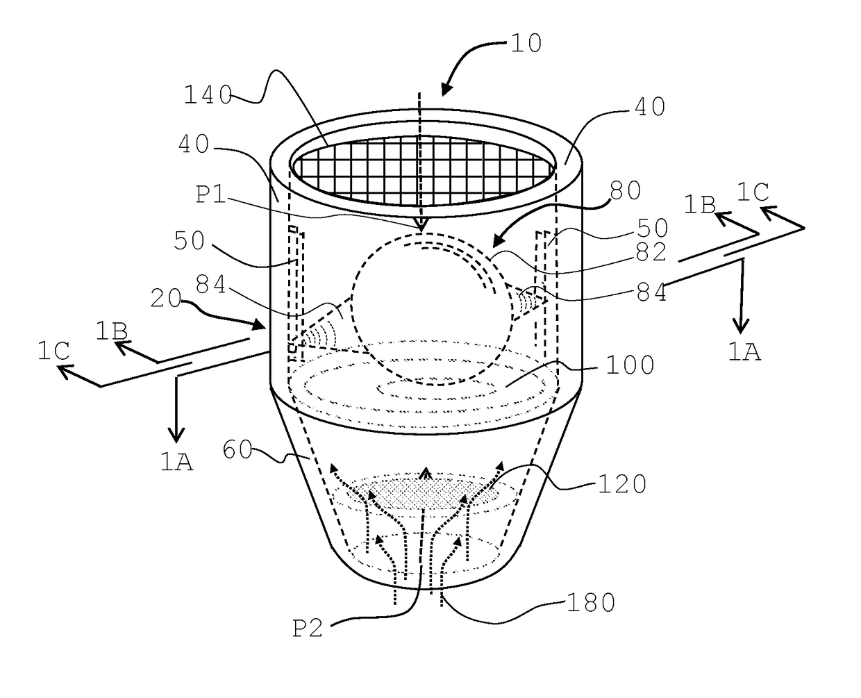
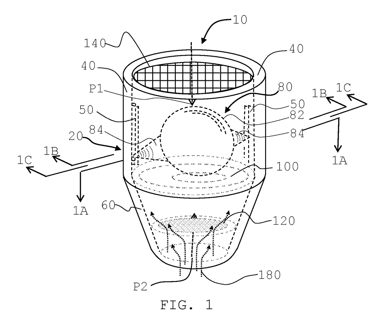
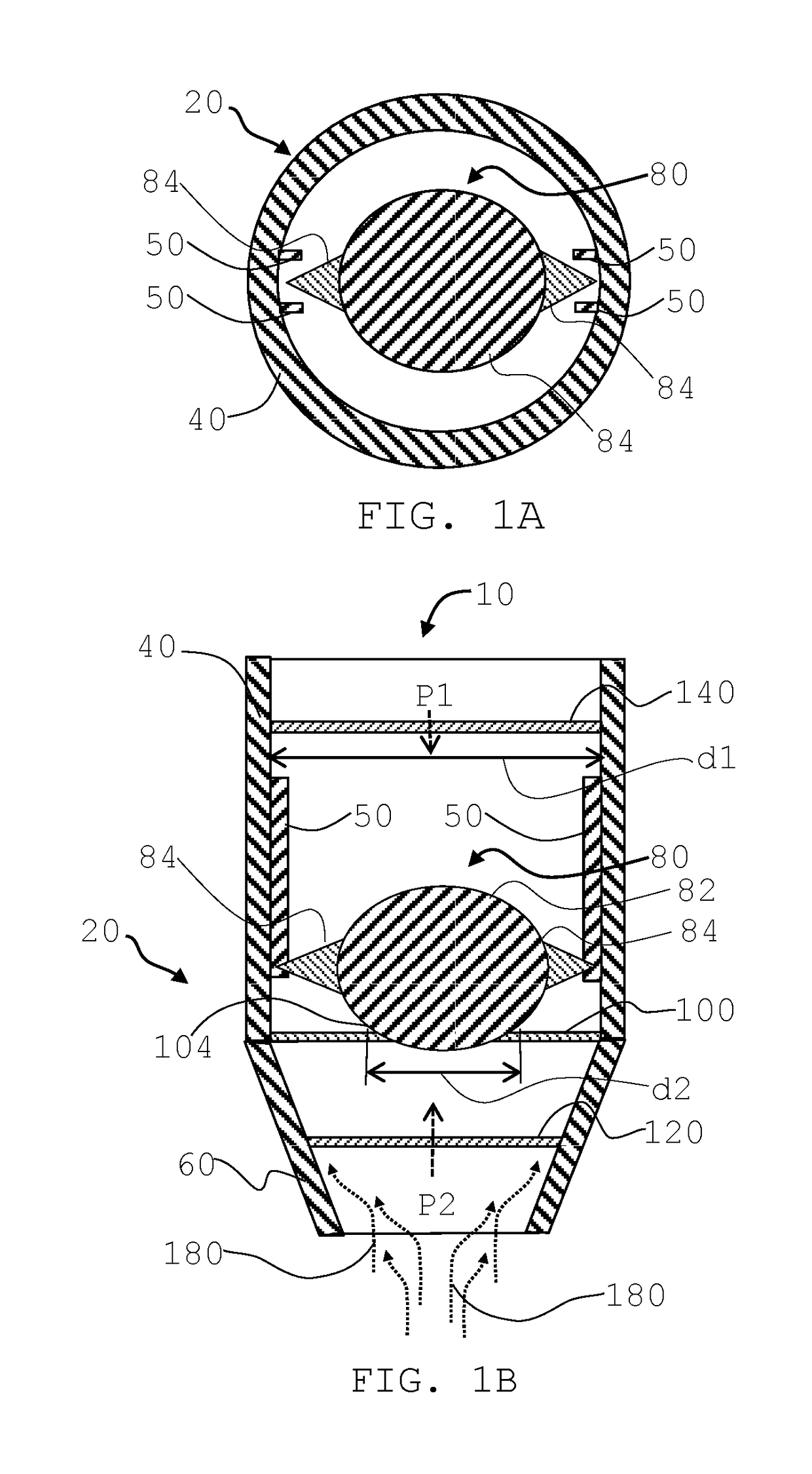
[0009]The apparatus is an invention that allows for the required volume of air to enter a piping system or an enclosed environment when there is a sufficient pressure difference between the ambient environment and the negative pressure in the piping system or an enclosed environment generating sufficient force to lift the rotary valve, the rotary valve will open and allow air / water flow to enter the piping system or enclosed environment. Therefore, the negative pressure will be eliminated.
[0010]When the piping system has radon gas, methane or other gas that generate positive pressure in the piping system or the enclosed environment the rotary valve will stay in the closed position and prevents radon gas, methane or other gas from leaving the piping system or the enclosed environment. The invention provides the proper seal by the rotary valve which has many advantage than the traditional flap valve. The rotation of the rotary valve will allow the contact points of the valve and the valve seat to constantly rotate and change, which will prolong the life of the valve. The rotation of the rotary valve will have less friction to move since rotational friction is less than static rotation. The rotation of the rotary valve will be less likely to be clogged and have less noise. The guide rail will allow the rotary valve to properly return back to the valve seat even when the air admittance and check valve is not installed vertically, which is a burdensome requirement for all other types of air admittance and check valves.

Problems solved by technology

The rotation of the rotary valve will allow the contact points of the valve and the valve seat to constantly rotate and change, which will prolong the life of the valve.
The guide rail will allow the rotary valve to properly return back to the valve seat even when the air admittance and check valve is not installed vertically, which is a burdensome requirement for all other types of air admittance and check valves.

Method used


Image

  • Air admittance and check valve
  • Air admittance and check valve
  • Air admittance and check valve

Examples


Embodiment Construction

[0033]Before the present invention is described in greater detail, it is to be understood that this invention is not limited to particular embodiments described, and as such may, of course, vary. It is also to be understood that the terminology used herein is for the purpose of describing particular embodiments only, and is not intended to be limiting, since the scope of the present invention will be limited only by the appended claims.

[0034]Where a range of values is provided, it is understood that each intervening value, to the tenth of the unit of the lower limit unless the context clearly dictates otherwise, between the upper and lower limits of that range is also specifically disclosed. Each smaller range between any stated value or intervening value in a stated range and any other stated or intervening value in that stated range is encompassed within the invention. The upper and lower limits of these smaller ranges may independently be included or excluded in the range, and ea...


PUM

PropertyMeasurementUnit
angleaaaaaaaaaa
Shore Hardnessaaaaaaaaaa
pressureaaaaaaaaaa

Abstract

An apparatus to allow or stop a flow into a piping system or an enclosed environment comprises (a) a housing having an upper flow passage and a lower flow passage; (b) a valve seat, wherein the valve seat is between the upper flow passage and the lower flow passage, wherein at least one opening is formed on the valve seat; (c) at least one rotary valve inside the housing, wherein each of the at least one rotary valve further comprises a main body and two guides mounted to the main body opposite to each other, and wherein the at least one rotary valve can move inside the upper flow passage and above the valve seat; and (d) at least two guide rails inside the upper flow passage for guiding each of the at least one rotary valve between an open position and a closed position.

Description

CROSS-REFERENCE RELATED TO RELATED APPLICATIONS[0001]This application is a continuation-in-part of commonly-owned, same inventor, presently U.S. Nonprovisional patent application Ser. No. 15 / 246,464, filed Aug. 24, 2016, which is incorporated herein by reference in its entirety. The Nonprovisional patent application Ser. No. 15 / 246,464 application is also a continuation-in-part of commonly-owned, same inventor, presently U.S. Nonprovisional patent application Ser. No. 15 / 132,131, filed Apr. 18, 2016, which is incorporated herein by reference in its entirety. U.S. Nonprovisional patent application Ser. No. 15 / 132,131 also claims the priority and benefit of US provisional patent application No. U.S. Provisional Application No. 62 / 151,463, filed Apr. 23, 2015.STATEMENT REGARDING FEDERALLY SPONSORED RESEARCH OR DEVELOPMENT[0002]Not ApplicableBACKGROUND[0003]A variety of air admittance valves have been made over the years for allowing air to enter a piping system or an enclosed environme...

Claims


Application Information

Patent Timeline
Patent Type & Authority Patents(United States)
IPC IPC(8): F16K15/04B01D46/00E03C1/122F16K27/02
CPCE03C1/1225F16K27/0209F16K15/048F16K15/042
Inventor DI MONTE, SR., MICHAEL ANTHONY
Owner DI MONTE MICHAEL A
Why Eureka
Try Eureka