
Gasket insertion method for mounting gasket inside outer cylinder of syringe, and gasket for mounting

a gasket and syringe technology, which is applied in the field of gasket and gasket insertion method for mounting gaskets inside the outer cylinder of syringes, can solve the problems of reducing the operability at the time, affecting the storage stability of drug solutions, and the inclination is more likely to occur at the time, so as to reduce the diameter of the syringe, increase the ratio of surface area per gasket volume, and increase the frictional resistan

Active Publication Date: 2018-07-24
TERUMO KK
View PDF15 Cites 2 Cited by
  • Summary
  • Abstract
  • Description
  • Claims
  • Application Information

AI Technical Summary

Benefits of technology

[0005]According to a conventional gasket insertion method that uses a sleeve, the axis of a gasket may become inclined with respect to the axis of the sleeve at the time of pushing the gasket by an inserter and inserting the gasket into the sleeve. Particularly, as the diameter of the syringe is reduced, the ratio of the surface area per gasket volume is increased and the frictional resistance is increased, and there is a problem that inclination is more likely to occur at the time of gasket insertion. In this case, the gasket is mounted inside the outer cylinder in an inclined state. This state where the gasket is inclined with respect to an outer cylinder affects the outer appearance of the prefilled syringe, and also increases the sliding resistance between the gasket and the outer cylinder, thereby reducing the operability at the time of use, and especially with respect to the prefilled syringe, this state possibly affects the storage stability of the drug solution that is filled inside.
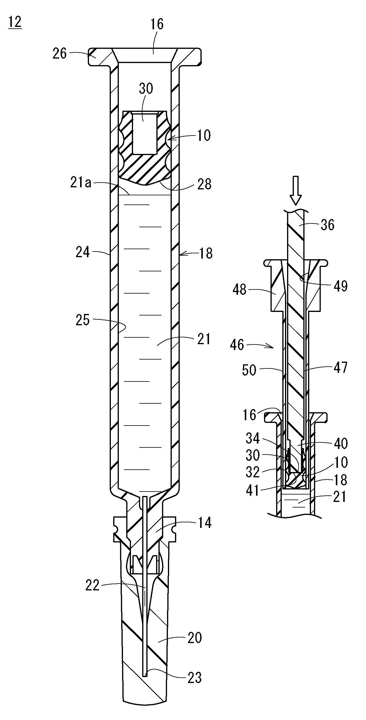
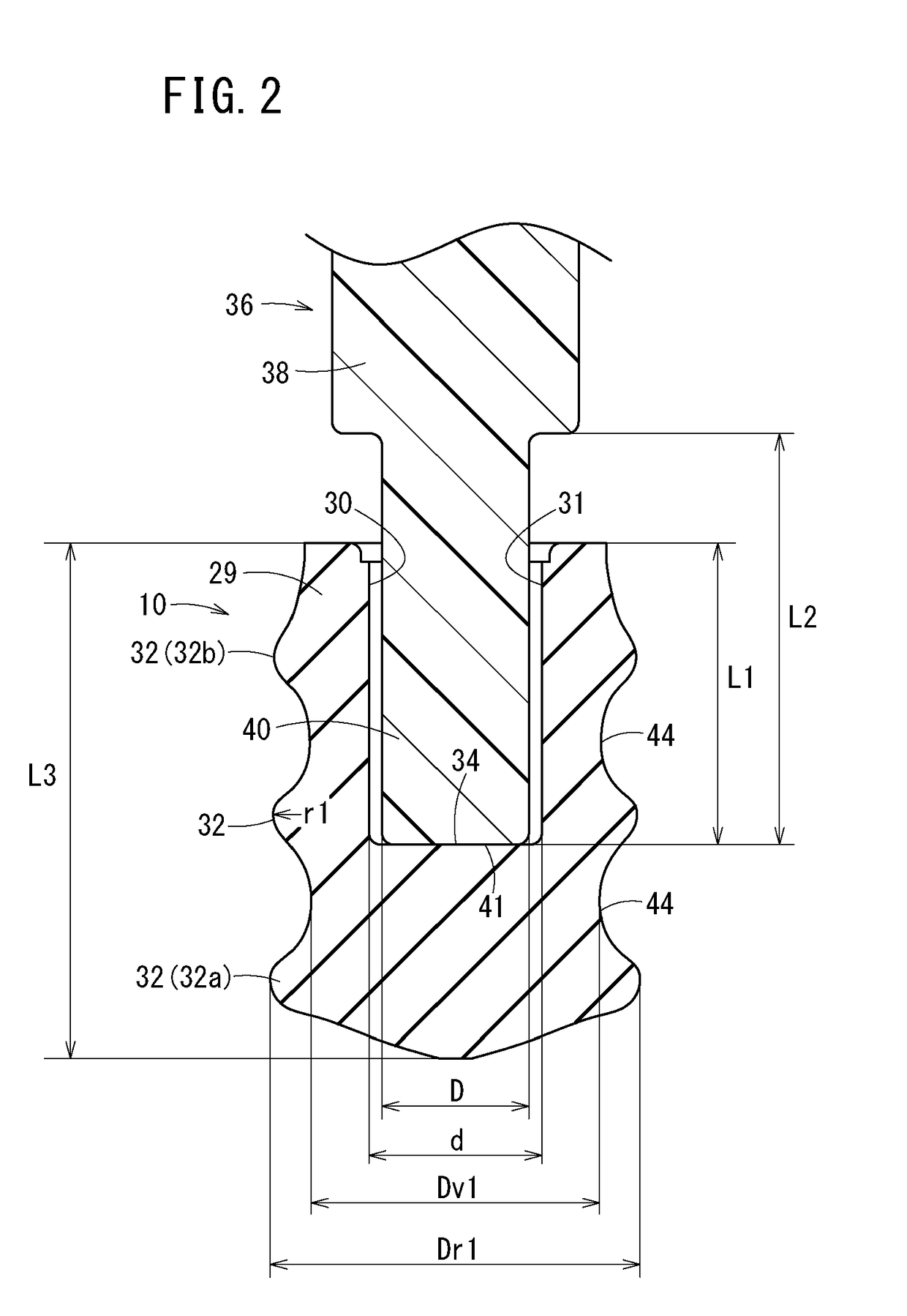
[0010]According to the above, the inner circumferential surface of the recessed section whose inner diameter is constant in the depth direction is supported by the outer circumferential surface of the tip end section of the inserter, and thus inclination of the gasket at the time of insertion of the gasket into the sleeve may be effectively suppressed.
[0012]According to the above, the tip end section of the inserter to be inserted into the recessed section of the gasket is relatively thick, and the gap between the outer circumferential surface of the tip end section of the inserter and the inner circumferential surface of the recessed section is small. Accordingly, inclination of the gasket at the time of insertion of the gasket into the sleeve may be effectively suppressed.
[0014]According to the above, inclination of the gasket may be suppressed in spite of the sliding resistance between the gasket and the outer cylinder.
[0016]According to the above, the circular ribs are provided at respective positions on the tip end side and the base end side with respect to the position (bottom surface) at which a pushing force from the inserter acts on the gasket. Accordingly, inclination of the gasket at the time of insertion of the gasket into the sleeve may be even more effectively suppressed.
[0020]According to the configuration described above, the circular ribs are provided at respective positions on the tip end side and the base end side with respect to the position (bottom surface) at which a pushing force from the inserter acts on the gasket. Accordingly, inclination of the gasket at the time of insertion of the gasket into the sleeve may be even more effectively suppressed.

Problems solved by technology

Particularly, as the diameter of the syringe is reduced, the ratio of the surface area per gasket volume is increased and the frictional resistance is increased, and there is a problem that inclination is more likely to occur at the time of gasket insertion.
This state where the gasket is inclined with respect to an outer cylinder affects the outer appearance of the prefilled syringe, and also increases the sliding resistance between the gasket and the outer cylinder, thereby reducing the operability at the time of use, and especially with respect to the prefilled syringe, this state possibly affects the storage stability of the drug solution that is filled inside.

Method used


Image

  • Gasket insertion method for mounting gasket inside outer cylinder of syringe, and gasket for mounting
  • Gasket insertion method for mounting gasket inside outer cylinder of syringe, and gasket for mounting
  • Gasket insertion method for mounting gasket inside outer cylinder of syringe, and gasket for mounting

Examples


Embodiment Construction

[0027]Hereinafter, embodiments of a gasket insertion method and a gasket according to the present invention will be described with reference to the appended drawings.

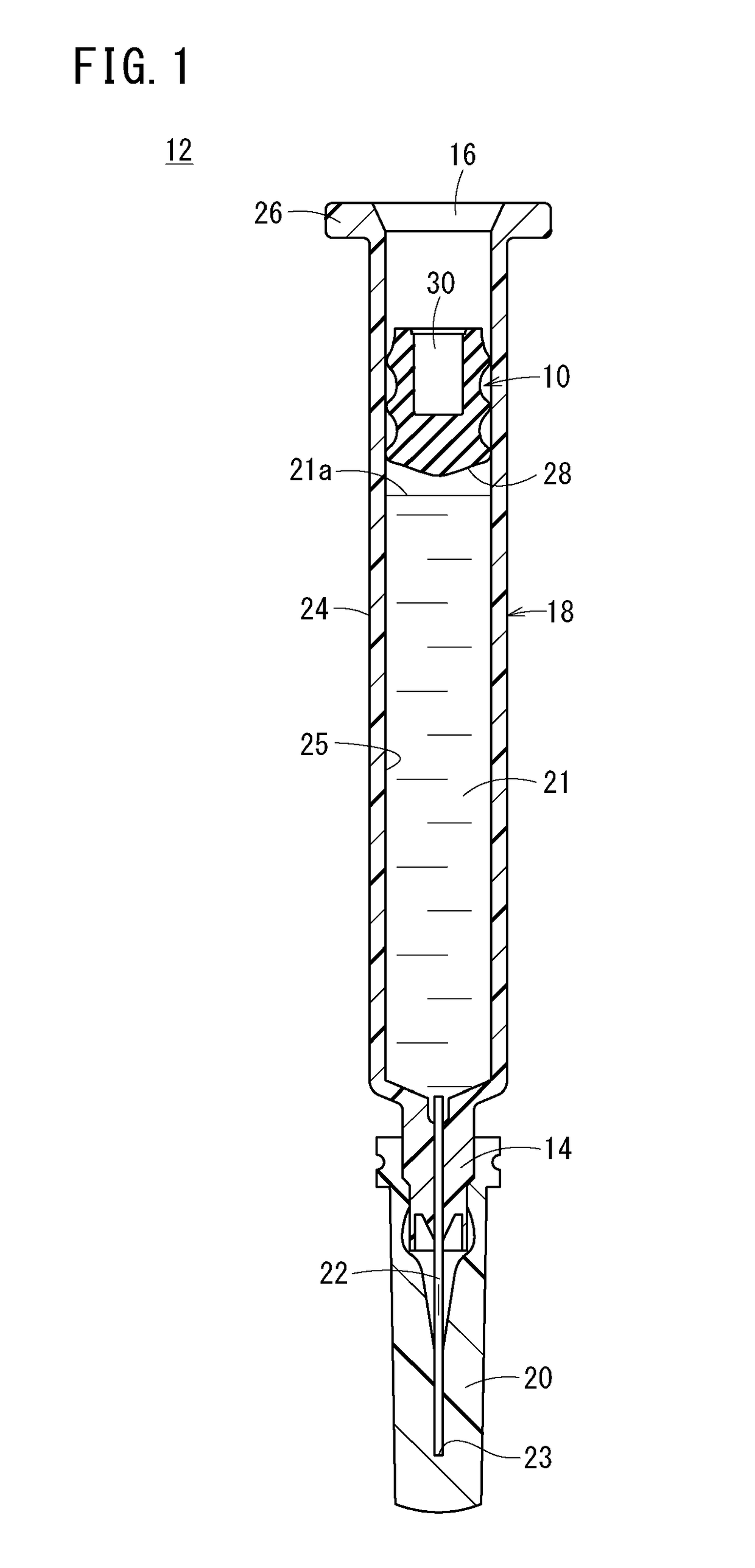
[0028]FIG. 1 is a longitudinal cross-sectional diagram illustrating an example configuration of a prefilled syringe 12 provided with a gasket 10 according to an embodiment of the present invention. The prefilled syringe 12 includes a cylindrical outer cylinder 18 having a cylinder tip section 14 and a base end opening section 16, a cap 20 for sealing the cylinder tip section 14, a drug solution 21 filling the outer cylinder 18, and the gasket 10 which is capable of sliding inside the outer cylinder 18.

[0029]The prefilled syringe 12 is formed as a syringe with a needle having a needle 22 fixed at the cylinder tip section 14. Additionally, the prefilled syringe 12 may be provided without the needle 22 (for example, the prefilled syringe may be configured such that a needle is attached before administration by Luer lock fi...


PUM


Abstract

A gasket insertion method for inserting a gasket into an outer cylinder includes providing an outer cylinder having a base end opening section; providing a gasket having a recessed section that is open at a base end of the gasket and that includes a flat bottom surface; pushing the gasket into a sleeve configured to be inserted into the outer cylinder, by relatively moving an inserter in a tip end direction with respect to the sleeve while a flat tip end surface of a tip end section of the inserter abuts the bottom surface of the recessed section; inserting the sleeve into the outer cylinder through the base end opening section; and arranging the gasket inside the outer cylinder by relatively moving the sleeve in a base end direction with respect to the outer cylinder while maintaining relative axial positions of the outer cylinder, the gasket, and the inserter.

Description

CROSS-REFERENCE TO RELATED APPLICATIONS[0001]This application is a continuation application filed under 35 U.S.C. § 111(a) claiming the benefit under 35 U.S.C. §§ 120 and 365(c) of PCT International Application No. PCT / JP2014 / 069799 filed on Jul. 28, 2014, which is based upon and claims the benefit of priority of Japanese Application No. 2013-156367 filed on Jul. 29, 2013, the entire contents of which are hereby incorporated by reference in their entireties.BACKGROUND OF THE INVENTION[0002]The present disclosure relates to a gasket and a gasket insertion method for mounting a gasket inside an outer cylinder of a syringe.[0003]Conventional methods for inserting a gasket into an outer cylinder in the process of manufacturing syringes and prefilled syringes include: a method of using a sleeve (mechanical capping), and a method of using a vacuum (vacuum capping). In the method of inserting a gasket in a prefilled syringe by using a sleeve, the gasket is first pushed by an inserter from ...

Claims


Application Information

Patent Timeline
Patent Type & Authority Patents(United States)
IPC IPC(8): F16J9/20A61M5/315B65B7/28
CPCF16J9/20A61M5/315B65B7/2821A61M2207/10A61M2207/00A61M5/31511
Inventor SHIMIZU, MAKOTOSASAMOTO, HAJIME
Owner TERUMO KK
Learn More