Voltage doubler with capacitor module for increasing capacitance

a capacitor module and voltage doubler technology, applied in the field can solve the problems of reducing the efficiency of the ac to dc adapter, reducing the efficiency of the dc to dc power converter, etc., to improve the efficiency of alternating current (ac), reduce the physical size, and reduce the voltage ripple

Active Publication Date: 2018-07-24
INFINEON TECH AUSTRIA AG
View PDF33 Cites 3 Cited by
  • Summary
  • Abstract
  • Description
  • Claims
  • Application Information

AI Technical Summary

Benefits of technology

[0003]In general, this disclosure is directed to techniques for reducing a physical size while improving the efficiency of alternating current (AC) to direct current (DC) adapters. In some examples, one or more techniques may permit use of capacitors having a low voltage rating rather than a high voltage rating to reduce a voltage ripple of a rectified AC voltage, thereby reducing a physical size of a resulting AC to DC adapter. For instance, an AC to DC adapter may selectively switch a capacitor having a low voltage rating (e.g., ˜100 volts) and a high capacitance (e.g., ˜56 μF) when a voltage of the rectified AC voltage is within a voltage threshold (e.g., ˜80%) of a voltage rating of the capacitor). In some examples, one or more techniques may increase a voltage received by a DC to DC power converter of an AC to DC adapter to improve the overall efficiency of the AC to DC adapter. For instance, an AC to DC adapter may selectively switch a series string of capacitors such that the DC to DC power converter of the AC to DC adapter receives a peak voltage that is greater than a peak voltage of the AC voltage received by the AC to DC adapter.

Problems solved by technology

However, the rectified AC voltage may include voltage ripples and a low peak voltage that reduces an efficiency of the DC to DC power converter, thereby resulting in a reduced efficiency of the AC to DC adapter.

Method used


Image

  • Voltage doubler with capacitor module for increasing capacitance
  • Voltage doubler with capacitor module for increasing capacitance
  • Voltage doubler with capacitor module for increasing capacitance

Examples


example 1

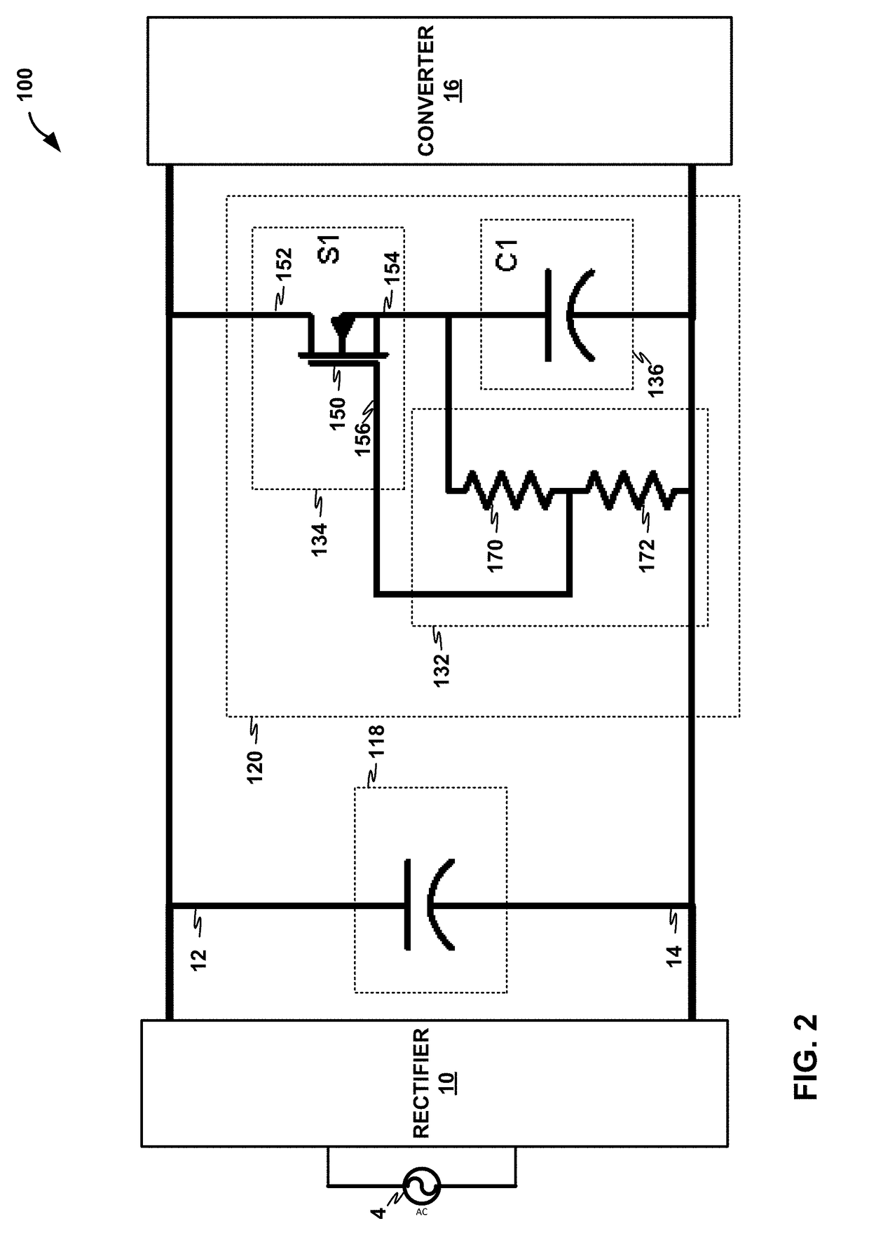
[0122]A circuit comprising: a voltage rail; a reference node; a first capacitor coupled to the voltage rail and to the reference node; and a capacitor module comprising: a second capacitor; and a switching unit configured to operate in a closed state and an open state, wherein the switching unit couples the second capacitor in parallel with the first capacitor in the closed state, and wherein the switching unit decouples the second capacitor from the first capacitor in the open state.

example 2

[0123]The circuit of example 1, further comprising: a voltage source coupled to the voltage rail and the reference node.

example 3

[0124]The circuit of any combination of examples 1-2, wherein: the switching unit comprises a voltage controlled circuit element including a first node coupled to the voltage rail, a second node, and a control node; and the second capacitor includes a first node coupled to the second node of the voltage controlled circuit element of the switching unit and a second node coupled to the reference node.


PUM


Abstract

In one example, a circuit includes an alternating current (AC) voltage source, a voltage rail, a reference rail, a first capacitor, a second capacitor, and a switching unit. The AC voltage source is configured to supply voltage in a first direction during a first half of a cycle and supply voltage in a second direction during a second half of the cycle. During a first state of the circuit, the voltage in the first direction supplied by the AC voltage source charges the first capacitor and the voltage in the second direction supplied by the AC voltage source charges the first capacitor. During a second state of the circuit, the voltage in the first direction supplied by the AC voltage source charges the first capacitor and the voltage in the second direction supplied by the AC voltage source charges the second capacitor.

Description

TECHNICAL FIELD[0001]This disclosure relates to alternating current (AC) to direct current (DC) adapters that receive an AC voltage and output a DC voltage.BACKGROUND[0002]Alternating current (AC) to direct current (DC) adapters may include a rectifier that receives an AC voltage and outputs a rectified AC voltage and a DC to DC power converter that receives the rectified AC voltage and outputs to a DC voltage suitable for electronic devices, such as laptops, mobile devices, tablets, and the like. However, the rectified AC voltage may include voltage ripples and a low peak voltage that reduces an efficiency of the DC to DC power converter, thereby resulting in a reduced efficiency of the AC to DC adapter.SUMMARY[0003]In general, this disclosure is directed to techniques for reducing a physical size while improving the efficiency of alternating current (AC) to direct current (DC) adapters. In some examples, one or more techniques may permit use of capacitors having a low voltage rati...

Claims


Application Information

Patent Timeline
Patent Type & Authority Patents(United States)
IPC IPC(8): H02M7/19H02M7/155H02M3/07H02M1/14H02M7/06H02M1/10
CPCH02M3/07H02M1/10H02M7/06H02M7/19H02M1/14H02M7/155H02M7/25H02J7/345
Inventor LEONG, KENNITH KINLIND, ANDERS
Owner INFINEON TECH AUSTRIA AG
Why Eureka
Try Eureka