Interbody fusion device with lipped anterior plate and associated methods

a fusion device and anterior plate technology, applied in the field of spinal fusion, can solve the problems of degeneration of the spine, pain and/or nerve damage, destabilization of the spine,

Active Publication Date: 2018-07-31
SPINESMITH PARTNERS
View PDF12 Cites 1 Cited by
  • Summary
  • Abstract
  • Description
  • Claims
  • Application Information

AI Technical Summary

Benefits of technology

[0007]An apparatus of the invention provides a spinal fusion device including a fusion bearing device configured to fit between two adjacent vertebrae, and a retention device configured to be secured to at least one of the adjacent vertebrae to prevent migration of the fusion bearing device, wherein the retention device has a height that is less than the height of the fusion bearing device.
[0011]The inventors have discovered that the fusion device as depicted in FIGS. 1-11, for example, which have zero profile anteriorly, can be improved upon for some applications. When such a fusion device is to be implemented in a patient using minimally invasive surgical techniques, there can be difficulty for the surgeon due to space and viewing limitations to affix the retention device to vertebrae because a large angle of approach is needed to screw in fasteners that enter the vertebrae, for example at a 35 degree angle. This angle can make screwing the fasteners in because of special flexible screw drivers must be used, for example, to enable a surgeon to drive the fasteners into the vertebrae. Likewise, long fasteners must be used because the portion of the vertebrae being accessed is relatively soft as compared to the bone of the apophyseal rings. Thus, other embodiments were developed by the inventors to create an anterior plate (retention device) that was still low profile but which permitted the fasteners to use the apophyseal rings for the fasteners, thereby permitting a lower angle of approach and shorter screws relative to the device of FIGS. 1-11. The improvement includes use of an anterior plate that has at least one lip that abuts and overhangs an apophyseal ring during use. The lip allows use of fasteners that can be driven through the apophyseal plates at an angle that need not be as great as an angle for the device of FIGS. 1-11. The lip is designed to abut the ring so that only a portion of the anterior plate is not zero profile. Furthermore, the anterior plate is a separate piece thereby permitting the load bearing component to be packed in situ with bone graft material. Likewise, the new anterior plate can be reversible. Moreover, the new anterior plate can be configured to permit multiple angles of approach in certain embodiments.

Problems solved by technology

Due to trauma, disease, and / or aging, the spine may be subject to degeneration.
This degeneration may destabilize the spine and cause pain and / or nerve damage.
One problem with prior art spinal fusion techniques relates to device migration.
In examples where bone screws are used, the insertion and tightening of the bone screws tends to cause device migration.
Another problem with typical prior art fusion techniques is that fusion devices, or associated plates or fasteners, protrude from the spine, causing discomfort, damage, or danger to surrounding vascular or neurological tissues.

Method used


Image

  • Interbody fusion device with lipped anterior plate and associated methods
  • Interbody fusion device with lipped anterior plate and associated methods
  • Interbody fusion device with lipped anterior plate and associated methods

Examples


Embodiment Construction

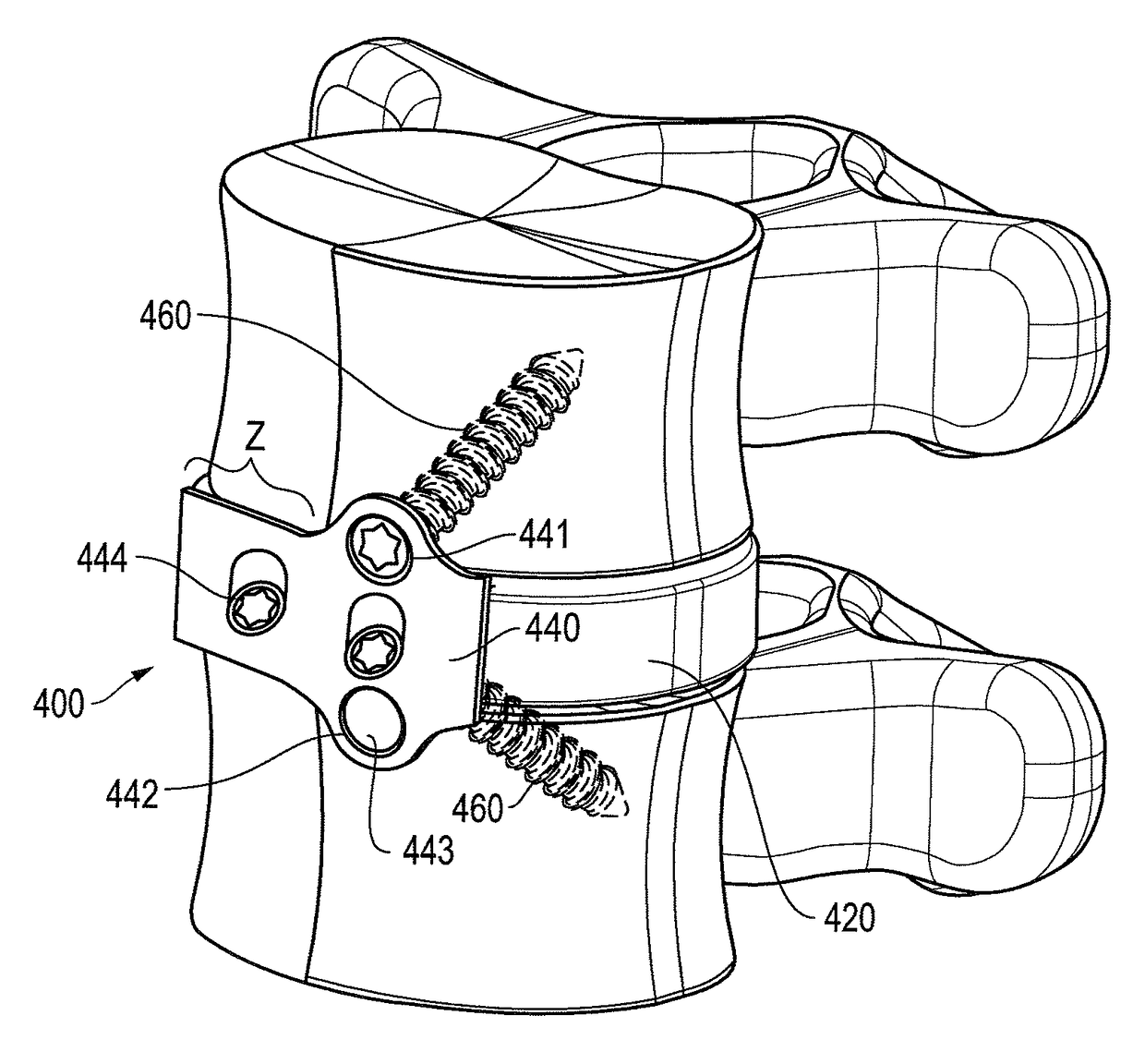
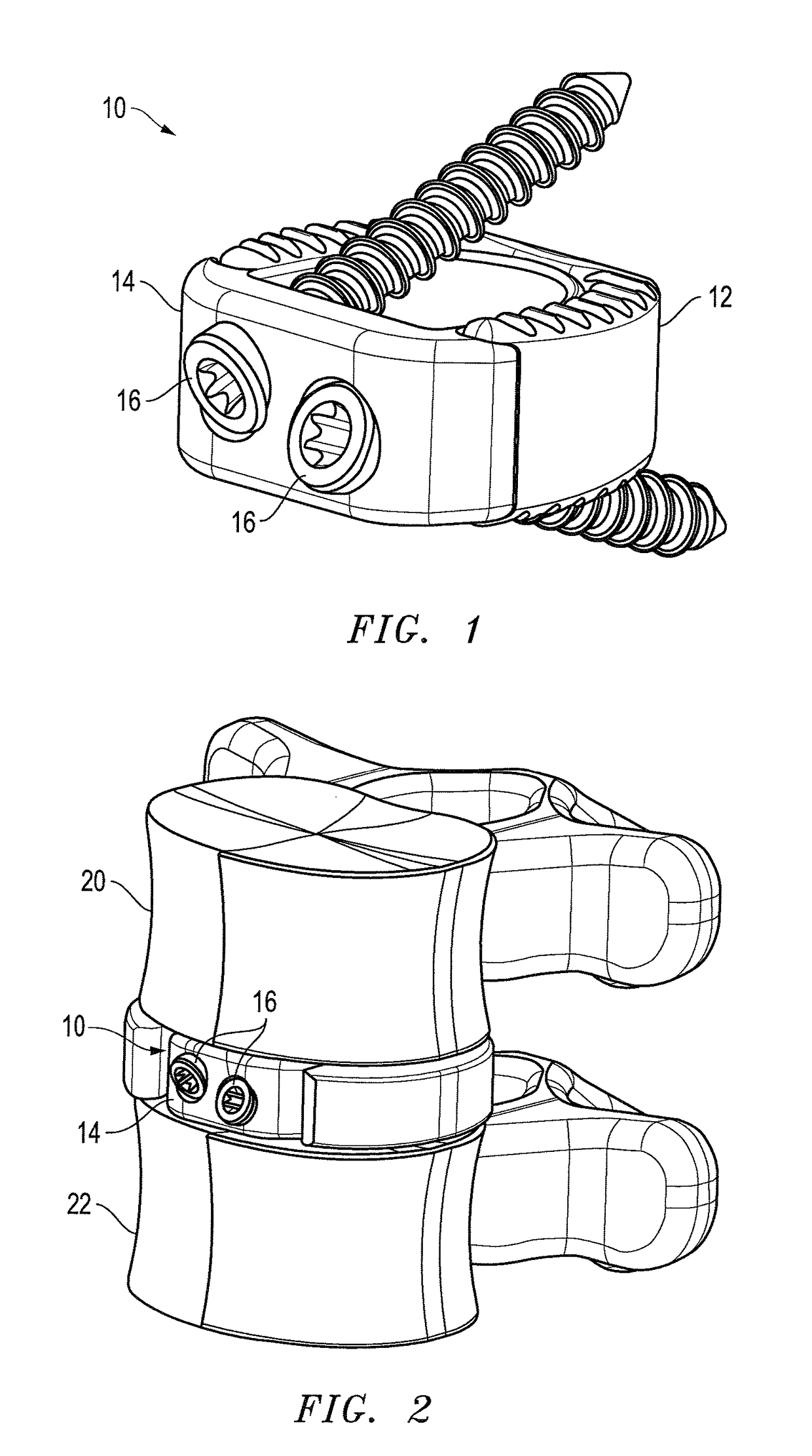
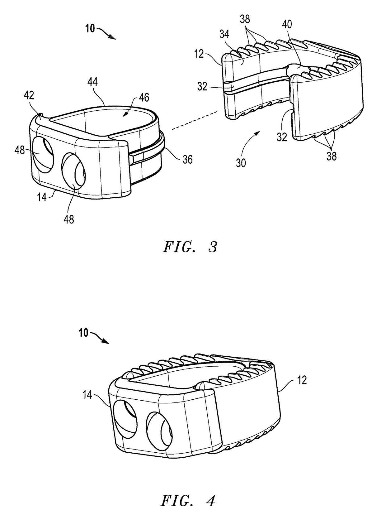
[0032]The present invention relates to spinal fusion implants and related spinal fusion procedures for use in cervical and lumbar applications. One type of spinal fusion is interbody fusion. Typically, an interbody fusion procedure places a bone graft between the vertebra in the area normally occupied by an intervertebral disc. In preparation for a spinal fusion procedure, the intervertebral disc is removed entirely. A device may be placed between the vertebra to maintain spine alignment and disc height. Fusion then occurs between the endplates of the vertebrae. In some examples, fusion is augmented by a process called fixation, meaning the placement of screws; rods or plates to stabilize the vertebra to facilitate bone fusion. The present invention provides an interbody fusion device that overcomes problems found in the prior art.

[0033]Generally, the present invention provides a two piece interbody fusion device that may be used with anterior lumbar interbody fusion (ALIF). In one ...


PUM


Abstract

A method and apparatus is provided for use in spinal fusion procedures. An interbody fusion device has a first piece that is a load bearing device designed to bear the axial loading from the end plates of adjacent vertebrae. A second piece of the interbody fusion device is a retention device whose function is to prevent migration of the load bearing device. One or more fasteners secure the retention device to the vertebrae above and below the load bearing device. The fasteners cause the end plates of the vertebrae to compress the end plates to the load bearing device to facilitate proper fusion. The second piece can be configured to include lips that abut the apothyseal rings during, with the plate including bores angled such that fasteners penetrate the apothyseal rings.

Description

CLAIM TO EARLIER APPLICATION[0001]This application claims priority to U.S. Provisional Patent Application No. 61 / 517,877, filed Apr. 27, 2011, and is a continuation-in-part of co-pending nonprovisional application Ser. No. 12 / 018,703, filed Jan. 23, 2008, which claims priority to provisional application Ser. No. 60 / 981,414, filed Oct. 19, 2007, and is a continuation-in-part of co-pending nonprovisional application Ser. No. 11 / 759,219, filed March, 2007, all of which are incorporated herein by referenceFIELD OF THE INVENTION[0002]This invention relates to the field of spinal fusion. In particular, this invention is drawn to spinal fusion devices and associated methods.BACKGROUND OF THE INVENTION[0003]The spine can be considered to be a series of movable segments made up of vertebrae and discs. Due to trauma, disease, and / or aging, the spine may be subject to degeneration. This degeneration may destabilize the spine and cause pain and / or nerve damage. Medical procedures are often requ...

Claims


Application Information

Patent Timeline
Patent Type & Authority Patents(United States)
IPC IPC(8): A61F2/44A61B17/86A61F2/30A61F2/28A61B17/80A61F2/46
CPCA61F2/4455A61F2/447A61F2/4465A61F2002/30352A61F2002/30349A61F2002/30372A61F2002/30373A61F2002/30383A61F2002/30387A61F2002/30397A61F2002/30482A61F2002/30507A61F2002/30509A61F2002/30517A61F2002/30578A61F2002/30604A61F2002/30607A61F2002/30616A61F2002/30774A61F2002/30782A61F2002/30904A61F2002/4475A61B17/8042A61B17/86A61F2/30744A61F2/4611A61F2002/2817A61F2002/2835A61F2002/302A61F2002/30131A61F2002/30355A61F2002/30593
Inventor KANA, RICHARDDUNWORTH, KEVINDUARTE, LUISBURKINSHAW, BRIANGUNDANNA, MUKUNDMEDEMA, RYAN
Owner SPINESMITH PARTNERS
Why Eureka
Try Eureka