Bellows with protective plate members

a technology of protective plate and belt, which is applied in the direction of manufacturing tools, mechanical equipment, metal-working machine components, etc., can solve the problems of affecting the accuracy of positioning, and piercing of belts, so as to effectively avoid the risk of loosening, and avoid the risk of accidental falling

Active Publication Date: 2018-07-31
NABERU KK
View PDF23 Cites 0 Cited by
  • Summary
  • Abstract
  • Description
  • Claims
  • Application Information

AI Technical Summary

Benefits of technology

[0032]According to the first invention (the invention described in Claim 1), as a result of disengagement of the one engagement parts or the one engagement members formed or arranged on the fixing plate, from the other engagement parts formed on the fitting plate part, the bellows with protective plate members now allows replacement of only damaged slat(s), rather than total replacement of the bellows, when damaged or deformed only in a part of a large number of fixed protective plate members (slats).
[0033]According to the bellows with protective plate members of the second invention (the invention described in Claim 2), since it is configured so that the third engagement part engages with the first engagement part when an external force is applied on the fitting plate part from the valley part side to the ridge part side; and so that the fourth engagement part engages with the second engagement part when an external force is applied on the fitting plate part from the ridge part side to the valley part side, so that there will be no risk of accidental fall of the protective plate member from the bellows body, even if the bellows body is stretched and contracted repetitively.
[0034]According to the bellows with protective plate members of the third invention (the invention described in Claim 3), by virtue of the elastic arm, the bellows not only makes it possible to effectively avoid a risk of accidental fall of the individual protective plate members attached to the fixing plate; but also to avoid a risk of loosening from the fixing plate during repetitive stretching and contraction of the bellows body, or when the bellows body is stretched or contracted instantaneously at a very high speed, a risk of generating noise or abnormal sound due to the loosening, and a risk of wearing of the individual engagement parts due to sliding contact between the first engagement part and the third engagement part, or between the second engagement part and the fourth engagement part.
[0035]According to the bellows with protective plate members of the fourth invention (the invention described in Claim 4), the protective plate member is restricted to move, relative to the fixing plate, in the direction of stretching and contraction of the bellows body, or, from the ridge part side to the valley part side, or from the valley part side to the ridge part side, and owing to the disk part, also restricted to move in the direction away from the fixing plate. As a consequence, the protective plate member may therefore be attached in a stable manner.
[0036]According to the bellows with protective plate members of the fifth invention (the invention described in Claim 5), since the stopper tongue is contained as a constituent, so that it now becomes possible to effectively avoid a risk of unintended shifting of the protective plate member, having the fitting plate part as a constituent, in the widthwise direction of the bellows body.
[0037]According to the bellows with protective plate members of the sixth invention (the invention described in Claim 6), attachment of the protective plate member to the fixing plate, and detachment of the protective plate member having been attached to the fixing plate, may be conducted sequentially from one end or from the other end of the fitting plate part or the protective plate member, and this greatly improves the workability of both processes.

Problems solved by technology

The bellows may also be broken or pierced, if it repeats stretching and contraction as the machine tool or the like operates over a long period, while carrying the grinding chips or debris caught between the ridge parts of the bellows, and the grinding chips or the like may adhere onto a ball screw or other driving system disposed inside the bellows, to thereby interfere with accurate positioning.

Method used


Image

  • Bellows with protective plate members
  • Bellows with protective plate members
  • Bellows with protective plate members

Examples


first embodiment

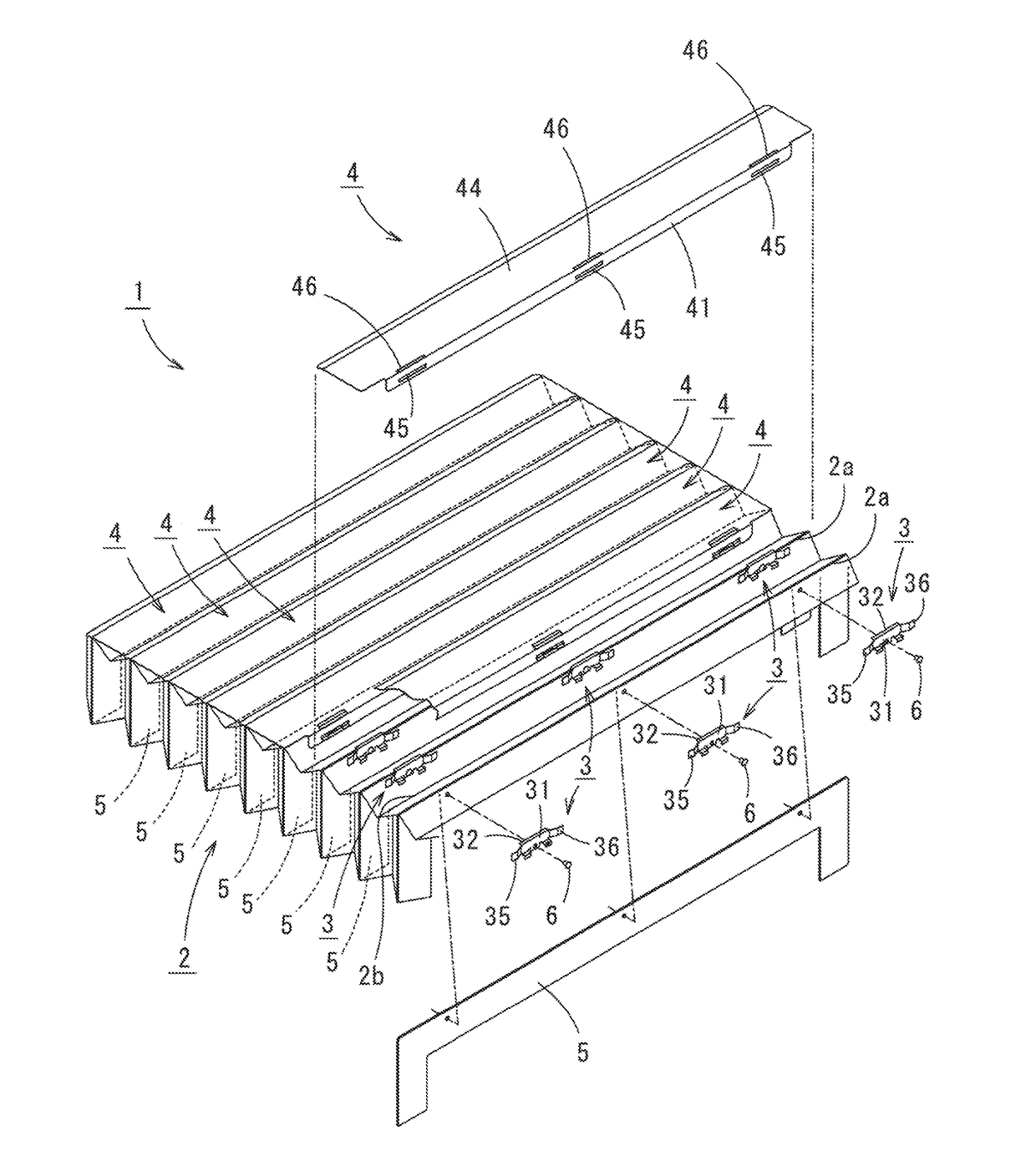
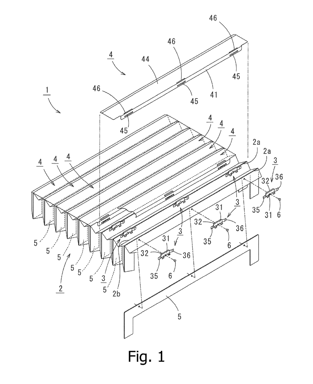
[0052]The bellows with protective plate members 1 has, as illustrated in FIG. 1, a bellows body 2, a plurality of fixing plates 3 attached to the bellows body 2, and protective plate members 4 detachably attached to these fixing plates 3.

[0053]The bellows body 2 is formed by pleating a resin sheet such as synthetic leather sheet, so as to alternately form ridge parts 2a and valley parts 2b, and has a main stretching / contraction part (reference sign not given) so that the ridge parts 2a and valley parts 2b respectively have the length in the horizontal direction, a left leg portion (reference sing not given) formed on the left side of the main stretching / contraction part and having the ridge parts 2a and the valley parts 2b alternately formed therein in the vertical direction (the direction normal to the ridge parts 2a), and a right leg portion formed on the right side of the main stretching / contraction part and having unillustrated ridge parts and the valley parts alternately forme...

second embodiment

[0064]Next, a bellows with protective plate members 51 according to this invention will be detailed referring to the drawings.

[0065]The bellows with protective plate members 51 according to the second embodiment has, as illustrated in FIG. 4, a bellows body 52 which is shaped and configured identically with the above-described bellows body 2, a plurality of fixing plates 35 fixed to the bellows body 52, and protective plate members (slats) 54 individually attached to the fixing plate 53 in a detachable manner. Inside the bellows body 52, there are fixed bellows supporting plates 55 which are configured identically with the above-described bellows supporting plates 5.

[0066]In the bellows with protective plate members 51 according to the second embodiment, a single fixing plate 53 having the length in the widthwise direction of the bellows body 52 is fixed to each ridge part 52a. The mode of fixation of each fixing plate 53 to the bellows body 52 is same as the mode of fixation of the...

third embodiment

[0074]Next, a bellows with protective plate members 71 according to this invention will be explained referring to the attached drawings.

[0075]The bellows with protective plate members 71 of the third embodiment has, as a constituent, protective plate members 74 illustrated in FIG. 9, in place of the protective plate members 54 which configure the bellows with protective plate members 51 of the second embodiment (all constituents other than the protective plate member 54 which configures the bellows with protective plate members 71 of the third embodiment will be explained below, using the same reference signs.). That is, each protective plate member 74 is configured by a fitting plate part 75 which is formed to have an approximately same width with the width of the bent plate part 59 formed in the fixing plate 53, an inclined plate part 77 which extends from the fitting plate part 75 across the first folded part 76, and a protective plate part 79 which extends from the inclined plat...


PUM


Abstract

[Subject] To provide a novel bellows with protective plate members, which allows replacement of only damaged slat(s), rather than total replacement of the bellows, when damaged or deformed only in a part of a large number of fixed slats (protective plate members).[Solving Means] The bellows includes a bellows body 2 having ridge parts 2a and valley parts 2b alternately formed therein, and having a bellows supporting plate 5 fixed inside thereof; a fixing plate 3 fixed to the bellows body 2; protective plate members 4 each having a fitting plate part 41 detachably attached to the fixing plate 3, and a protective plate 44; wherein the fixing plate 3 having formed therein one engagement parts 33, 34, the fitting plate part 41 having formed thereon other engagement part 45, 46, thereby making it possible to attach or detach the protective plate member 4 to and from the fixing plate 3.

Description

TECHNICAL FIELD[0001]This invention relates to a bellows with protective plate members, which is attached to equipment or apparatus, such as machine tools including machining center, lathe and milling machine, and semiconductor manufacturing equipment including dicing machine.BACKGROUND ART[0002]Welding or grinding of metal using a machining center, milling machine or the like, often scatters spatter, grinding chips or coolant, and a dicing machine scatters chips of diced semiconductor wafer. The scattered matters when adhered on a bellows of the equipment or apparatus may pierce the bellows. The bellows may also be broken or pierced, if it repeats stretching and contraction as the machine tool or the like operates over a long period, while carrying the grinding chips or debris caught between the ridge parts of the bellows, and the grinding chips or the like may adhere onto a ball screw or other driving system disposed inside the bellows, to thereby interfere with accurate positioni...

Claims


Application Information

Patent Timeline
Patent Type & Authority Patents(United States)
IPC IPC(8): B23Q11/08F16P3/02F16P1/00
CPCF16P3/02B23Q11/0816B23Q11/0825B24B55/04H01L21/02
Inventor YAGAMI, YUUSUKEMATSUOKA, YOSHINORI
Owner NABERU KK
Why Eureka
Try Eureka