Plasma processing apparatus

a processing apparatus and plasma technology, applied in the direction of coatings, chemical vapor deposition coatings, electric discharge tubes, etc., can solve the problems of insufficient measurement of waveforms for a short time, above-the-radar technology has encountered problems, etc., to achieve the effect of improving processing yield and processing precision and high precision

Active Publication Date: 2018-07-31
HITACHI HIGH-TECH CORP
View PDF8 Cites 0 Cited by
  • Summary
  • Abstract
  • Description
  • Claims
  • Application Information

AI Technical Summary

Benefits of technology

[0015]It is an object of the present invention to provide a plasma processing apparatus with improved processing precision and increased yield.
[0018]The above configuration allows selection of a period in which the plasma is in a steady state and a period in which the plasma is in a transient state, thereby to detect the plasma state with higher precision. Based on this, the plasma processing apparatus can be operated or the plasma processing conditions can be adjusted, and the apparatus state and the plasma processing conditions can be monitored. In particular, processing yield and processing precision can be improved by detecting and using plasma characteristics such as the time until self bias occurs, a maximum value and a minimum value of plasma density, and the rise time of the plasma density from the high-frequency bias waveform in the transient state.

Problems solved by technology

The above prior art has encountered problems due to insufficient consideration for the following points.
However, if the period that the plasma is in the transient state is short, it is not enough to simply measure the waveform for the short time.

Method used


Image

  • Plasma processing apparatus
  • Plasma processing apparatus
  • Plasma processing apparatus

Examples


first embodiment

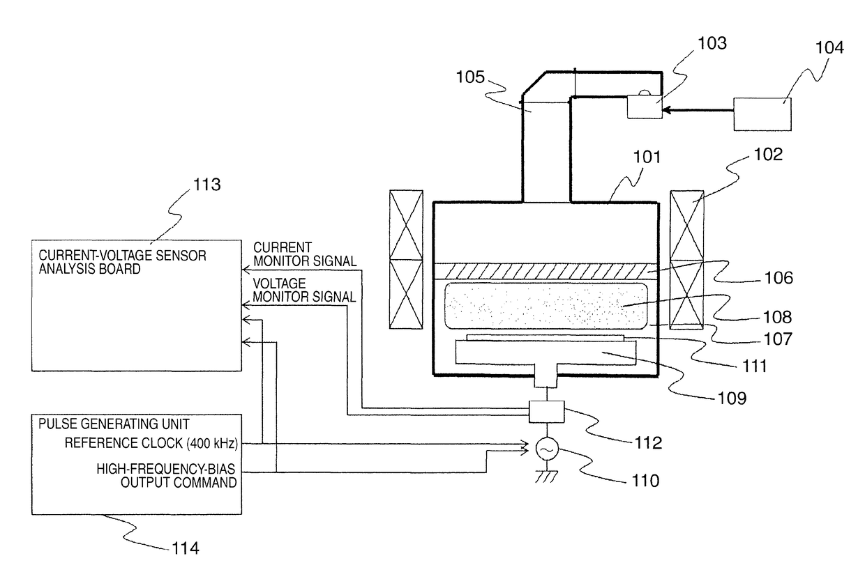
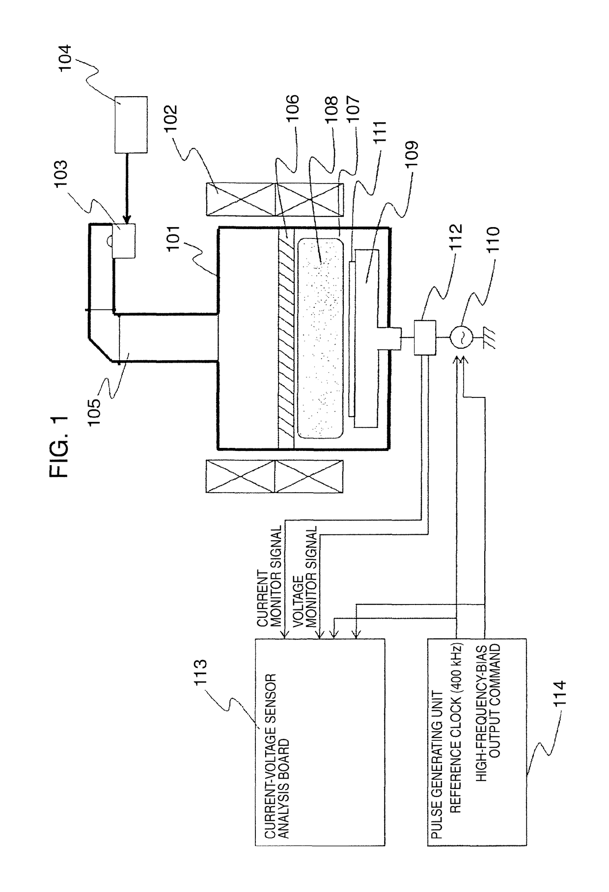
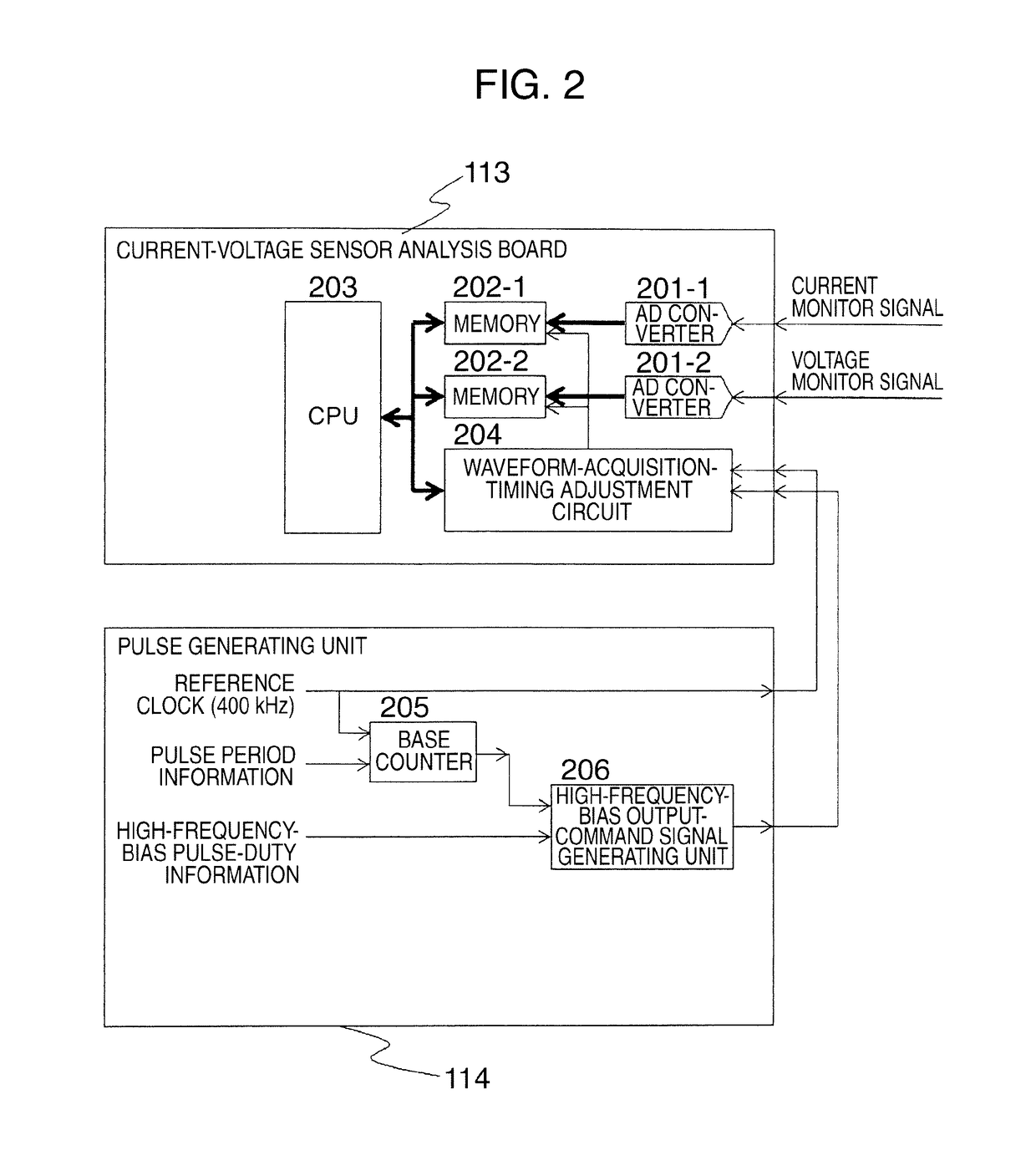
[0032]The first embodiment of the present invention will be described with reference to FIGS. 1 to 3, and 9FIG. 1 is a longitudinal sectional view schematically illustrating an outline of a structure of a plasma processing apparatus according to the embodiment of the present invention.

[0033]The plasma processing apparatus according to the present embodiment introduces electric and magnetic fields for generating a plasma in a processing chamber disposed inside a vacuum vessel to excite the atoms or molecules of a process gas supplied into the processing chamber thereby to generate the plasma. According to such present embodiment, electrons moving in the electric field of a high frequency such as microwave and a VHF / UHF band introduced into the processing chamber are subject to cyclotron motion in a magnetic field also introduced therein. Thus, the plasma can be efficiently generated by selecting the magnetic field strength and the high-frequency electric field frequency so as to reso...


PUM

PropertyMeasurementUnit
timeaaaaaaaaaa
time delayaaaaaaaaaa
frequencyaaaaaaaaaa

Abstract

The plasma processing apparatus includes: a processing chamber disposed inside a vacuum vessel; a first high-frequency power supply outputting a first high-frequency power for supplying an electric field to generate a plasma for use in processing a sample to be processed inside the processing chamber; a sample stage disposed inside the processing chamber with the sample placed on an upper surface thereof; a second high-frequency power supply intermittently outputting a second high-frequency power for generating a bias potential to an electrode disposed inside the sample stage and capable of variably adjusting the output time; and a function to adjust operation of the plasma processing apparatus using a result of detection of a temporal change in waveform of current or voltage in a transient state of the second high-frequency power in synchronism with start of the intermittent output of the second high-frequency power.

Description

BACKGROUND OF THE INVENTION[0001]The present invention relates to a plasma processing apparatus and a plasma processing method for processing a substrate-like sample such as a semiconductor wafer disposed in a processing chamber disposed inside a vacuum vessel using a plasma generated in the processing chamber, and more particularly to a plasma processing apparatus and a plasma processing method for processing a sample by forming a high-frequency-bias potential on the sample using high-frequency power supplied to an electrode disposed inside a sample stage on which the sample is placed.[0002]As one of the processes of fabricating semiconductor devices in prior art techniques, there has been used a technique for forming a circuit wiring structure using a plasma for etching a plurality of film layers including masks disposed on a surface of a substrate-like sample such as a semiconductor wafer. Examples of such prior art techniques using plasma include a plasma processing apparatus th...

Claims


Application Information

Patent Timeline
Patent Type & Authority Patents(United States)
IPC IPC(8): C23C16/00C23F1/00H01L21/306H01J37/32
CPCH01J37/32146H01J37/32935H01J37/32192
Inventor TOYOTA, KOJIYAMAMOTO, KOICHIYASUI, NAOKI
Owner HITACHI HIGH-TECH CORP
Why Eureka
Try Eureka