Systems and methods for virtual aperature radar tracking

a technology of radar tracking and aperture, applied in the field of radar, can solve problems such as limited traditional solutions

Active Publication Date: 2018-08-14
OCULII CORP
View PDF25 Cites 33 Cited by
  • Summary
  • Abstract
  • Description
  • Claims
  • Application Information

AI Technical Summary

Problems solved by technology

These traditional solutions are limited: angular resolution depends both on the

Method used


Image

  • Systems and methods for virtual aperature radar tracking
  • Systems and methods for virtual aperature radar tracking
  • Systems and methods for virtual aperature radar tracking

Examples


Embodiment Construction

[0021]The following description of the invention embodiments of the invention is not intended to limit the invention to these invention embodiments, but rather to enable any person skilled in the art to make and use this invention.

1. Method for Virtual Aperture Array Radar Tracking

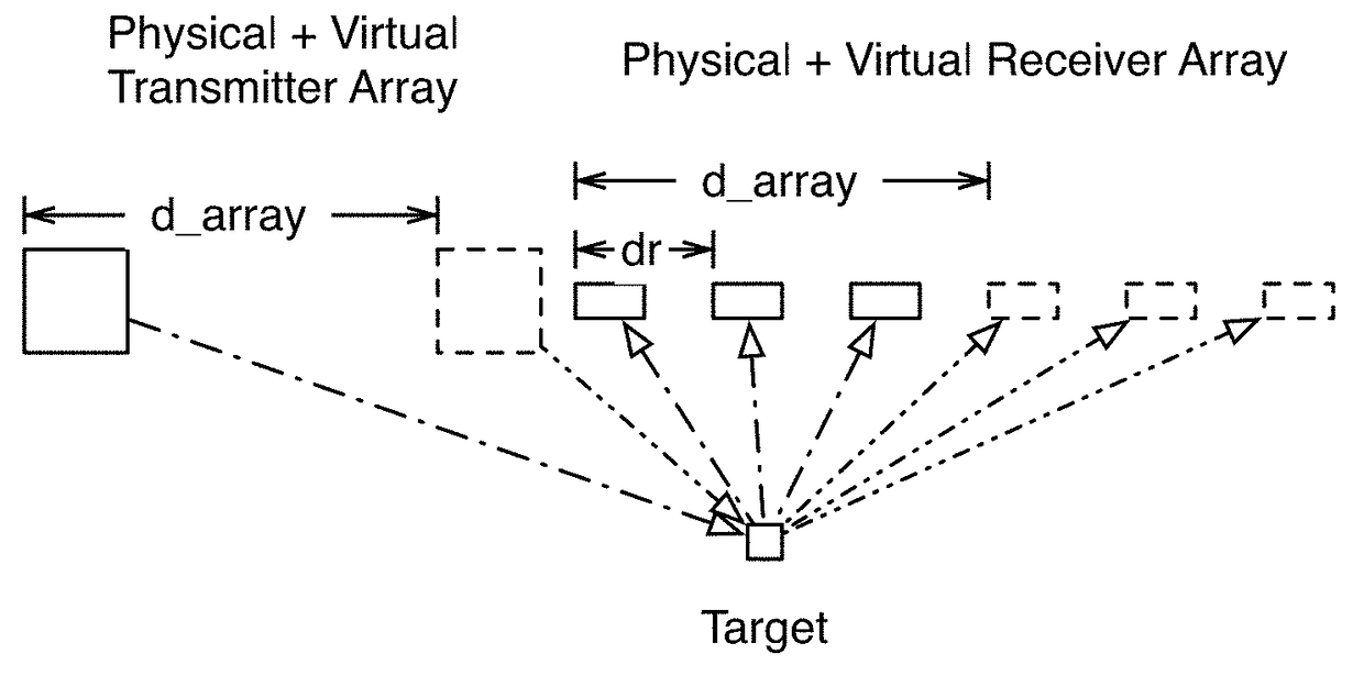
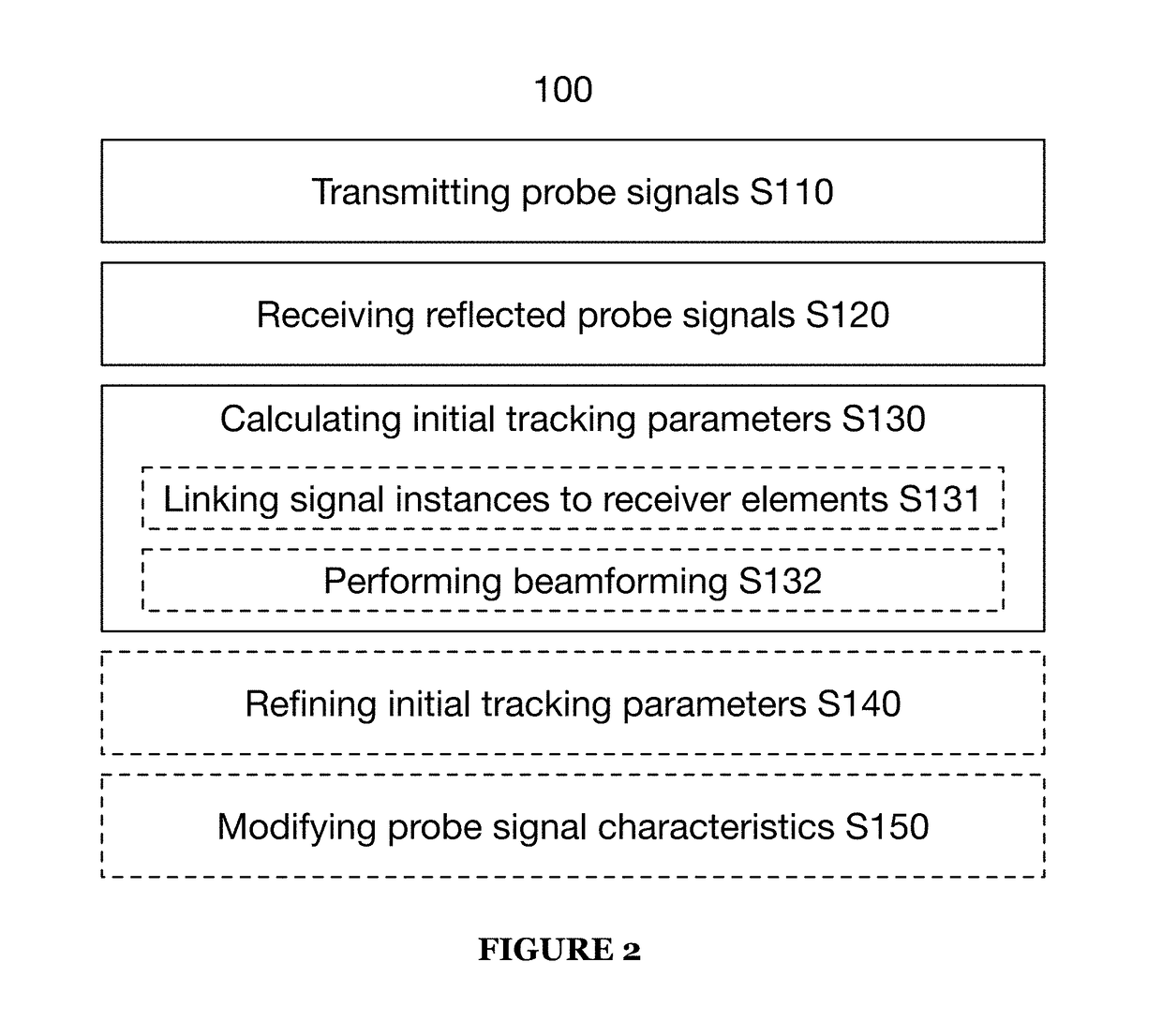
[0022]A method 100 for virtual aperture array (VAA) radar tracking includes transmitting a set of probe signals S110, receiving a set of reflected probe signals S120, and calculating initial tracking parameters from the set of reflected probe signals S130, as shown in FIG. 2. The method 100 may additionally include refining the initial tracking parameters S140 and / or modifying probe signal characteristics S150.

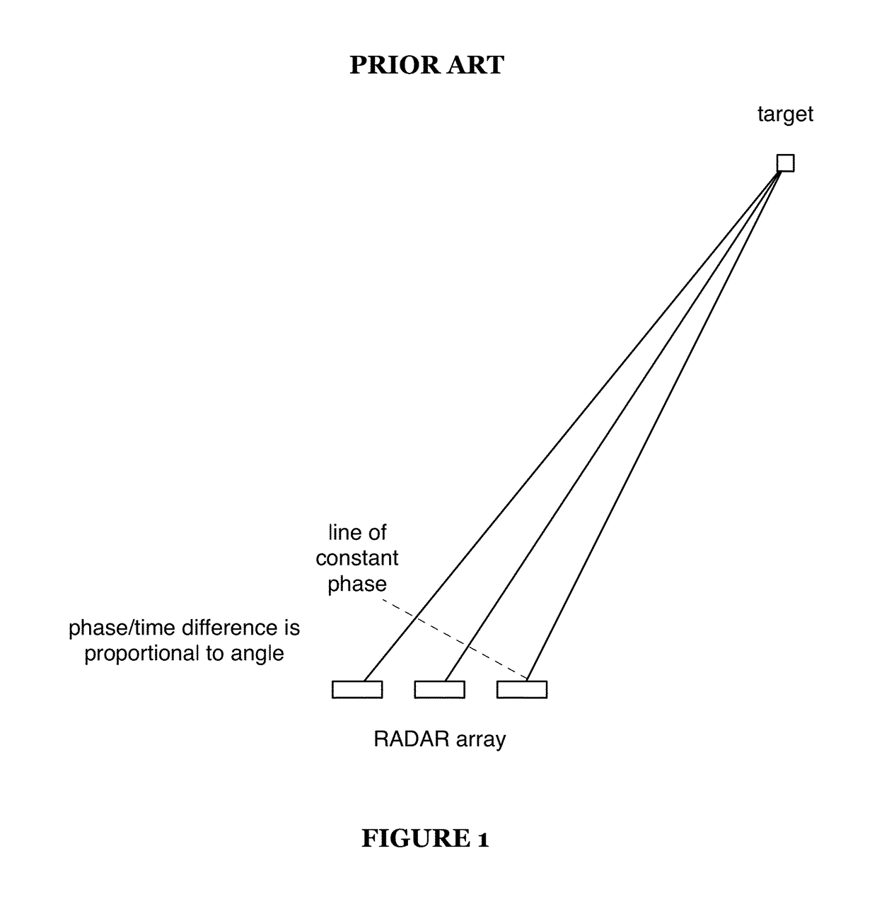
[0023]As discussed in the background section, traditional array-based radar systems are limited: angular resolution depends both on the number of elements in the receiver array and the angle between the array and the target:

[0024]θresolution≈λNd⁢⁢cos⁢⁢θ

where N is the number of elements in the array a...


PUM


Abstract

A method for virtual aperture array radar tracking includes: transmitting first and second probe signals; receiving a first reflected probe signal at a radar array; receiving a second reflected probe signal at the radar array; calculating a target range from at least one of the first and second reflected probe signals; corresponding signal instances of the first reflected probe signal to physical receiver elements of the radar array; corresponding signal instances of the second reflected probe signal to virtual elements of the radar array; calculating a first target angle by performing beamforming from the signal instances of the first and second reflected probe signals; and calculating a position of the tracking target relative to the radar array from the target range and first target angle.

Description

TECHNICAL FIELD[0001]This invention relates generally to the radar field, and more specifically to new and useful systems and methods for virtual aperture radar tracking.BACKGROUND[0002]Traditional array-based receivers calculate azimuth and / or elevation by measuring the time or phase difference between received probe signals at different receivers (or antennas) within the array(s), as shown in FIG. 1 (1D array), using beamforming (e.g., digital beamforming). Similar effects may be produced using a transmit array instead of a receiver array. These traditional solutions are limited: angular resolution depends both on the number of elements in the array and the angle between the array and the target:[0003]θresolution≈λNd⁢⁢cos⁢⁢θwhere N is the number of elements in the array and d is the distance separating them.[0004]Thus, there is a need in the radar field to create new and useful systems and methods for virtual aperture radar tracking. This invention provides such new and useful sys...

Claims


Application Information

Patent Timeline
IPC IPC(8): G01S13/72G01S13/00G01S7/42G01S13/44G01S7/52
CPCG01S7/42G01S13/003G01S13/723G01S13/4463G01S7/52023G01S7/52019G01S13/66G01S13/86G01S13/90G01S13/931G01S15/66G01S2013/0263G01S2013/9323G01S2013/9322G01S2013/932G01S2013/9324G01S2013/9316G01S13/72G01S13/934
Inventor HONG, LANGHONG, STEVEN
Owner OCULII CORP
Why Eureka
Try Eureka