Thermostatic valve

a technology of thermostatic valves and valve bodies, applied in the direction of machines/engines, process and machine control, instruments, etc., can solve the problems of inability to reproduce kinematics, and achieve the effects of improving kinematics, simple and cost-effective construction, and stable design

Active Publication Date: 2018-08-14
DR ING H C F PORSCHE AG
View PDF19 Cites 0 Cited by
  • Summary
  • Abstract
  • Description
  • Claims
  • Application Information

AI Technical Summary

Benefits of technology

[0006]Described herein is a thermostatic valve which has a stable design in comparison to the thermostatic valves from the prior art and is nevertheless constructed simply and cost-effectively and has improved kinematics.
[0011]It is particularly advantageous if the housing is acted upon in the axial direction by a force accumulator, wherein the force accumulator is arranged supported between the valve housing and the housing or the switching element.

Problems solved by technology

This arrangement of the bearings may lead to tilting of the actuator, if the sealing connection and guidance of the piston rod into the housing of the actuator are not optimally formed, thus resulting in kinematics which are not reproducible.

Method used


Image

  • Thermostatic valve
  • Thermostatic valve
  • Thermostatic valve

Examples


Embodiment Construction

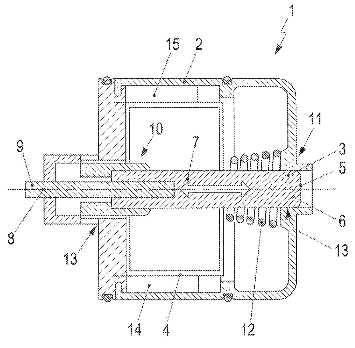
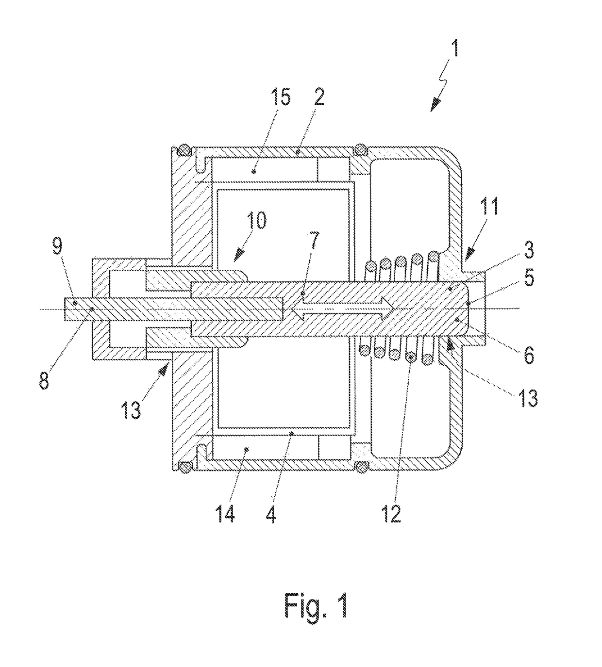
[0020]FIG. 1 shows an exemplary embodiment of a valve 1 with a valve housing 2 and an actuator 3 arranged therein. The actuator 3 has a housing 5 with a cylinder space 6 which is defined therein and has a medium filling 7. A piston rod or a plunger 8 protrudes into the housing 5 of the actuator.

[0021]The actuator is fixed in the valve housing 2 via the plunger 8 or the piston rod in such a manner that the distal end 9 of the plunger 8 is fixed in the valve housing while the housing 5 of the actuator 3 is mounted in a sliding manner in the valve housing 2. For this purpose, the housing 5 is accommodated slidably at its distal end regions 10, 11 in a receptacle in the valve housing. The housing 5 is mounted slidably within the valve housing 2 by plain bearings 13.

[0022]The valve 1 has a switching element 4 which is of cylinder-like or cup-like design and which is connected to the housing 5 of the actuator.

[0023]The housing 5 of the actuator 3 is arranged shiftably in the axial directi...


PUM


Abstract

A thermostatic valve with a valve housing having a fluid inlet and a fluid outlet, with an actuator which is accommodated in the valve housing and has a housing, and with a switching element which is operatively connected to the actuator in order to control a fluid connection between fluid inlet and fluid outlet, wherein a plunger protrudes out of the housing, the plunger being connected in an axially fixed manner to the valve housing, and the housing being accommodated in an axially shiftable manner in the valve housing, wherein the housing is mounted in the region of its opposite end regions in the valve housing by plain bearings, wherein the switching element is arranged in an axially displaceable manner relative to the housing of the actuator.

Description

CROSS-REFERENCE TO RELATED APPLICATIONS[0001]This application claims priority under 35 U.S.C. § 119 of German Patent Application No. 10 2013 111 618.3, filed Oct. 22, 2013, which is incorporated by reference herein in its entirety.FIELD OF THE INVENTION[0002]The invention relates to a thermostatic valve with an actuator for actuating a switching element.BACKGROUND OF THE INVENTION[0003]Various thermostatic valves, in particular for the coolant circuit of a motor vehicle, have been disclosed in the prior art. DD 96 766, which is incorporated by reference herein, and DE 1917 925, which is incorporated by reference herein, each disclose a thermostatic valve with an actuator having an expansion material filling, in which an actuating piston is accommodated in a housing filled with the expansion material and protrudes out of the housing with a piston rod or a plunger, wherein the end side of the piston rod or plunger is mounted in the housing of the thermostat. When the expansion materia...

Claims


Application Information

Patent Timeline
Patent Type & Authority Patents(United States)
IPC IPC(8): G05D23/02
CPCG05D23/022G05D23/026G05D23/024F01P7/16F16K17/38G05D23/025
Inventor GEFFERT, THOMASBLUM, FRANK
Owner DR ING H C F PORSCHE AG
Why Eureka
Try Eureka