Stator for rotating electric machine

a technology of rotating electric machines and rotating shafts, which is applied in the direction of dynamo-electric machines, electrical apparatus, windings, etc., can solve the problems of insulation failure, electric conductors to be exposed from the insulating coat, etc., and achieves sufficient creepage distance and increased clearance

Active Publication Date: 2018-08-14
DENSO CORP
View PDF8 Cites 6 Cited by
  • Summary
  • Abstract
  • Description
  • Claims
  • Application Information

AI Technical Summary

Benefits of technology

[0017]With the above configuration, by arranging the apex parts of each of the pairs to axially overlap each other, it becomes possible to considerably (twice or more in comparison with the conventional stators) increase the clearance between each circumferentially-adjacent pair of the apex parts of the turn portions of all the phase windings. Consequently, even when the electric conductors are exposed at the apex parts due to damage to the insulating coats, it is still possible to secure a sufficient creepage distance between the apex parts. In addition, since each axially-overlapping pair of the apex parts are included in the same one of the phase windings, the difference in electric potential between the apex parts is small, thus making it difficult for creeping discharge to occur therebetween.

Problems solved by technology

Therefore, at the crank-shaped parts 154 to which a high stress is applied during the press-shaping process, the insulating coats of the electric wires may be damaged, causing the electric conductors to be exposed from the insulating coats.
Consequently, creeping discharge (or surface discharge) may occur between those portions of the phase windings of the stator coil 140 where the electric conductors are exposed, thus resulting in an insulation failure.
Therefore, at the crank-shaped parts 154 to which a high stress is applied during the press-shaping process, the insulating coats of the electric conductor segments may be damaged, causing the electric conductors to be exposed from the insulating coats.
Consequently, creeping discharge may occur between those portions of the phase windings of the stator coil 240 where the electric conductors are exposed, thus resulting in an insulation failure.
In addition, since each axially-overlapping pair of the apex parts are included in the same one of the phase windings, the difference in electric potential between the apex parts is small, thus making it difficult for creeping discharge to occur therebetween.

Method used


Image

  • Stator for rotating electric machine
  • Stator for rotating electric machine
  • Stator for rotating electric machine

Examples


Embodiment Construction

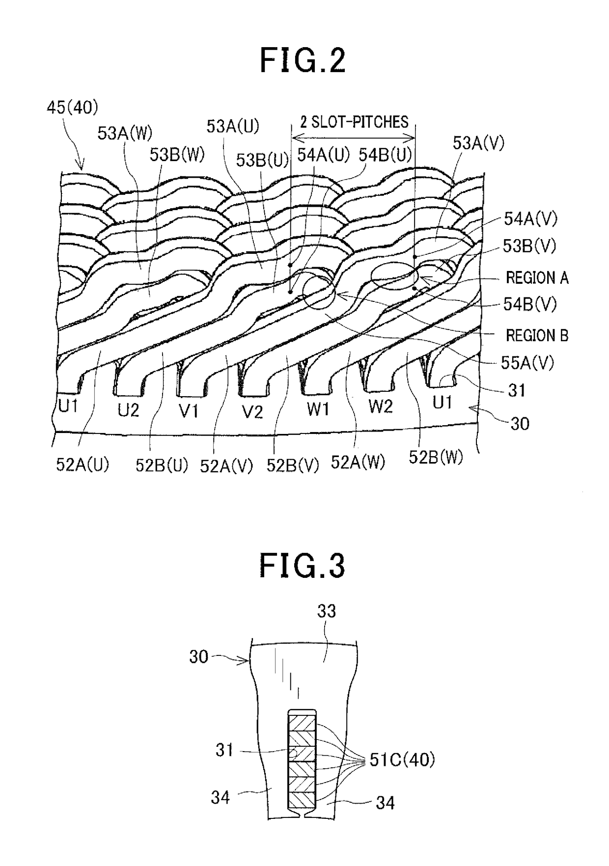
[0038]FIG. 1 shows the overall configuration of a rotating electric machine 1 which includes a stator 20 according to an exemplary embodiment.

[0039]The rotating electric machine 1 is designed to be used in a motor vehicle, such as a passenger car or truck, as an electric motor.

[0040]As shown in FIG. 1, the rotating electric machine 1 further includes a housing 10 and a rotor 14 in addition to the stator 20. The housing 10 is comprised of a pair of cup-shaped housing pieces 10a and 10b which are jointed together at the open ends thereof. The housing 10 has a pair of bearings 11 and 12 mounted therein, via which a rotating shaft 13 is rotatably supported by the housing 10. The rotor 14 is received in the housing 10 and fixed on the rotating shaft 13. The stator 20 is fixed in the housing 10 so as to surround the radially outer periphery of the rotor 14.

[0041]The rotor 14 includes a plurality of permanent magnets that form a plurality of magnetic poles on the radially outer periphery o...


PUM


Abstract

A stator includes a stator core having slots arranged in a circumferential direction thereof at a predetermined pitch and a stator coil comprised of phase windings. Each of the phase windings is configured with an electric conductor and an insulating coat covering the electric conductor. Each of the phase windings includes in-slot portions and turn portions connecting the in-slot portions. The turn portions of the phase windings include a plurality of types of turn portions having different circumferential lengths. For each of the phase windings, apex parts of the turn portions of the phase winding are arranged in pairs over the entire circumferential range of the stator coil. The apex parts of each of the pairs axially overlap each other. Each circumferentially-adjacent pair of the apex parts of the turn portions of all the phase windings are circumferentially offset from each other by a distance greater than the predetermined pitch.

Description

CROSS-REFERENCE TO RELATED APPLICATION[0001]This application is based on and claims priority from Japanese Patent Application No. 2015-30647 filed on Feb. 19, 2015, the content of which is hereby incorporated by reference in its entirety into this application.BACKGROUND[0002]1. Technical Field[0003]The present invention relates to stators for rotating electric machines that are used in, for example, motor vehicles as electric motors and electric generators.[0004]2. Description of Related Art[0005]There are known rotating electric machines that are used in motor vehicles as electric motors and electric generators. These rotating electric machines generally include a rotor and a stator. The stator includes an annular stator core and a stator coil. The stator core is disposed in radial opposition to the rotor and has a plurality of slots arranged in a circumferential direction thereof. The stator coil is comprised of a plurality of phase windings that are mounted on the stator core so ...

Claims


Application Information

Patent Timeline
Patent Type & Authority Patents(United States)
IPC IPC(8): H02K3/12H02K3/38H02K3/28
CPCH02K3/28H02K3/12H02K3/38H02K1/165H02K3/04H02K2213/03
Inventor TAMURA, AKITO
Owner DENSO CORP
Why Eureka
Try Eureka