Communication system
a communication system and communication technology, applied in the field of communication systems, can solve the problems of insufficient data rate and increased cost, and achieve the effects of reducing noise, avoiding the degradation of sound quality, and increasing cos
- Summary
- Abstract
- Description
- Claims
- Application Information
AI Technical Summary
Benefits of technology
Problems solved by technology
Method used
Image
Examples
first embodiment
[0023](First Embodiment)
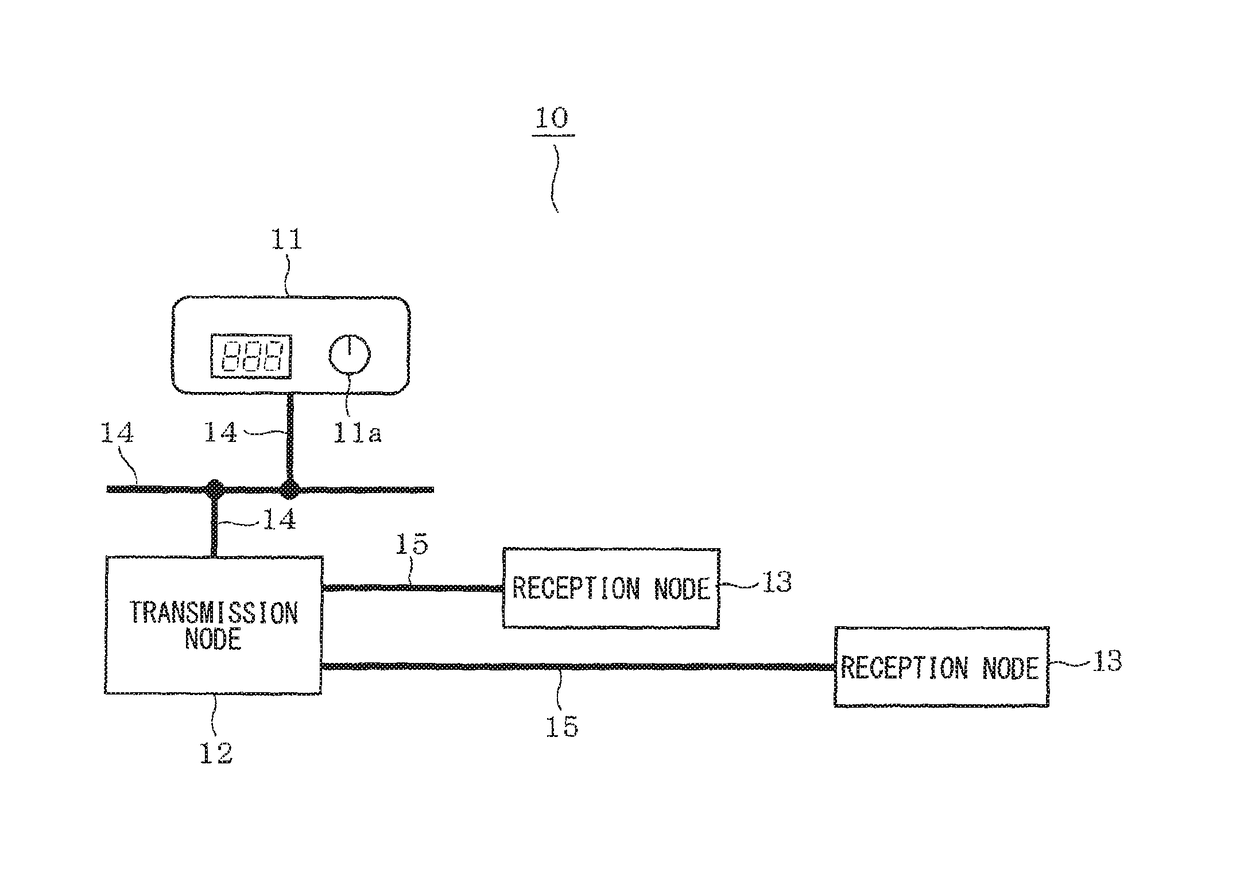
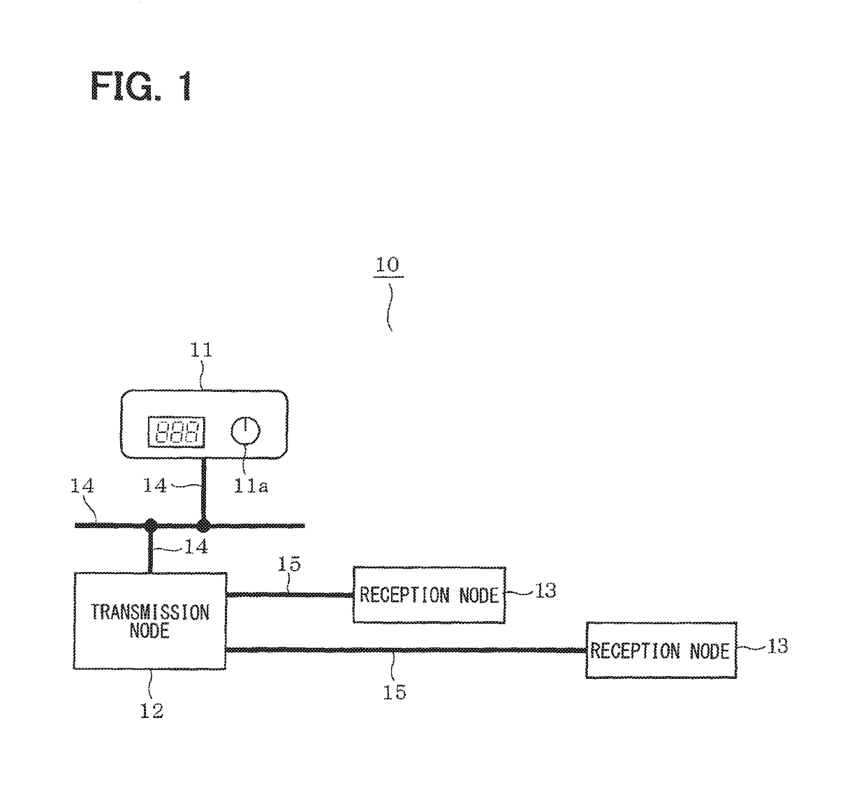
[0024]A communication system 10 illustrated in FIG. 1 is mounted in a vehicle, and includes a vehicle radio 11, a transmission node 12, and a reception node 13. The vehicle radio 11 is an example of a radio wave receiver and includes an operation unit 11a for selecting a channel. The transmission node 12 and the reception node 13 are communication nodes for building an in-vehicle LAN. In this case, the vehicle radio 11 and the transmission node 12 are communicably connected to each other by a wired communication cable 14 for low-speed communication. In this case, the transmission node 12 and the reception node 13 are communicably connected to each other by a wired communication cable 15 for high-speed communication.
[0025]When a user selects the channel through the operation unit 11a, the vehicle radio 11 notifies the transmission node 12 of a selected frequency packet indicating a frequency corresponding to the selected channel through the wired communication...
second embodiment
[0035](Second Embodiment)
[0036]In the present embodiment, when a transmission node 12 changes the transmission rate according to the selected frequency of a vehicle radio 11, as shown in FIG. 6, the transmission node 12 adds preamble data Db to a data body Da to be transmitted to a reception node 13. The preamble data Db is an example of transmission rate information indicating the changed transmission rate. In this case, the preamble data Db is configured by, for example, “0101 . . . ” data of 10 bits.
[0037]The reception node 13 specifies the changed transmission rate based on the preamble data Db obtained from the transmission node 12. In this case, the reception node 13 specifies the changed transmission rate based on a toggle pattern of the preamble data Db. In other words, the reception node 13 specifies the changed transmission rate according to a length of time required for receiving, for example, 10-bit preamble data Db. When the reception node 13 specifies the changed trans...
third embodiment
[0039](Third Embodiment)
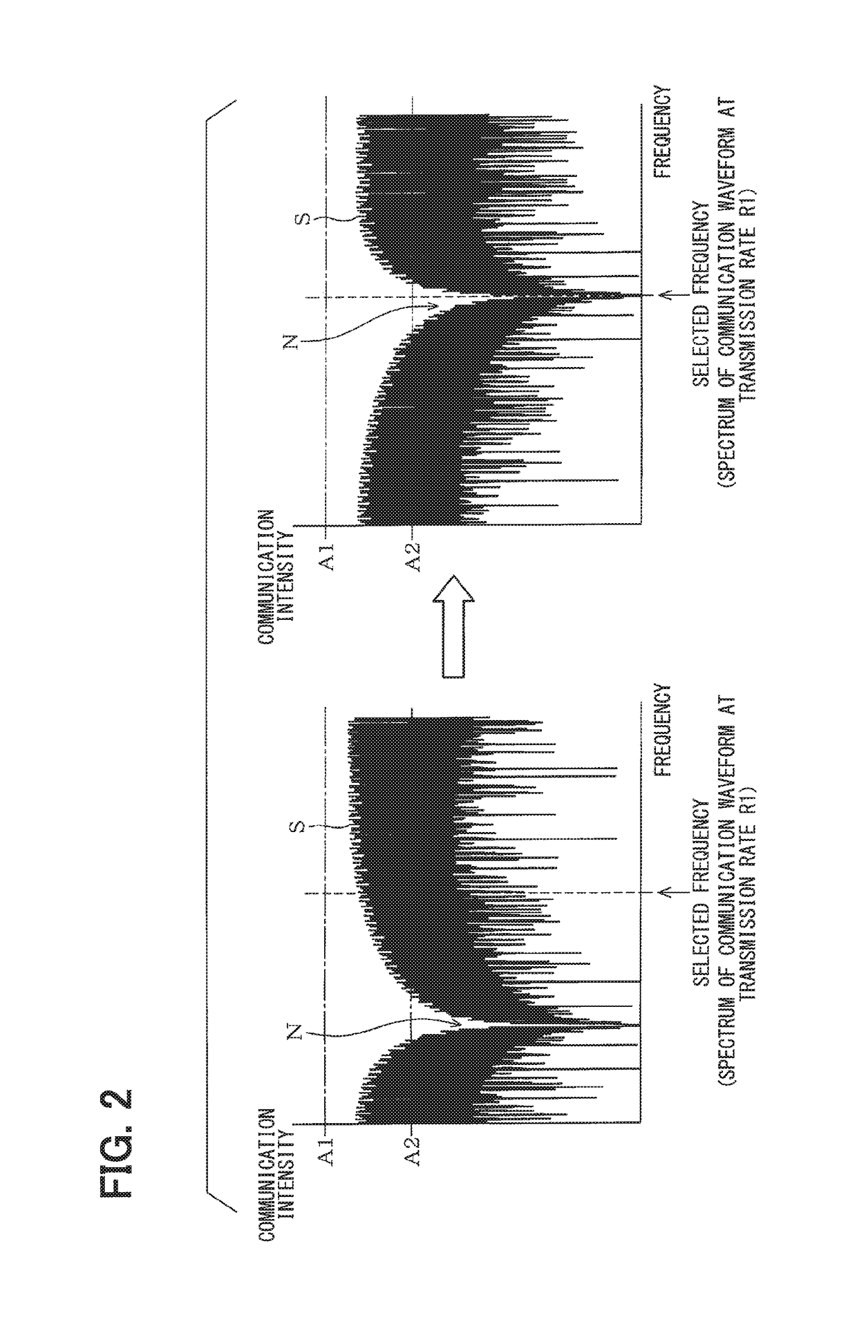
[0040]According to a communication system 20 illustrated in FIG. 7, a reception node 13 is also communicably connected to a vehicle radio 11 through a wired communication cable 14 for a low speed communication. In this configuration, when the selected frequency is changed, as shown in FIG. 8, the vehicle radio 11 notifies a transmission node 12 and the reception node 13 of a selected frequency packet F indicating a selected frequency through the wired communication cable 14. The transmission node 12 that has received the selected frequency packet F adjusts the transmission rate based on the frequency indicated by the selected frequency packet F, and the reception node 13 that has received the selected frequency packet F adjusts the receiving rate based on the frequency indicated by the selected frequency packet F As a result, the transmission-reception rates of data between the transmission node 12 and the reception node 13 are changed from a rate R1 that doe...
PUM
 Abstract
Description
Claims
Application Information
 - R&D
- Intellectual Property
- Life Sciences
- Materials
- Tech Scout
- Unparalleled Data Quality
- Higher Quality Content
- 60% Fewer Hallucinations
Browse by: Latest US Patents, China's latest patents, Technical Efficacy Thesaurus, Application Domain, Technology Topic, Popular Technical Reports.
© 2025 PatSnap. All rights reserved.Legal|Privacy policy|Modern Slavery Act Transparency Statement|Sitemap|About US| Contact US: help@patsnap.com


