Firearm and firearm buffer assembly

a buffer assembly and firearm technology, applied in the field of automatic or semiautomatic firearms, can solve the problems of increasing the manufacturing cost of weapons, and adding complexity and cost to weapons

Inactive Publication Date: 2018-08-21
TCC SOLUTIONS
View PDF18 Cites 6 Cited by
  • Summary
  • Abstract
  • Description
  • Claims
  • Application Information

AI Technical Summary

Benefits of technology

[0004]In an effort to enable over the beach capability of the AR15 / M16 family of weapons and their derivatives several modifications to the weapon have been attempted. One example, of providing over the beach capability is through the use of specially designed (i.e. not in a stock configuration) bolt carriers and receiver extension tubes. The specially designed bolt carriers generally include water-draining cots at the rear of the bolt carrier which increases the manufacturing cost of the weapon. The specially designed receiver extension tubes include drainage holes provided on the underside and at the rear of the receiver extension tube. The drainage holes in the receiver extension tube also increase manufacturing costs of the weapon as these drainage holes are not included in the standard base configuration of the weapon. Other attempts to provide over the beach capability include providing a selector at the end of the receiver extension tube that allows the user of the weapon to select an aperture size for allowing water drainage out of the receiver extension tube. This variable drainage aperture selector also adds complexity and cost to the weapon.
[0005]It would be advantageous to have a water / fluid drainage capability that may be retrofitted to existing weapons in their stock configuration (e.g. with conventional stock configuration bolt carriers and stock configuration receiver extension tubes) without breaking down the weapon beyond field stripping.

Problems solved by technology

The specially designed bolt carriers generally include water-draining cots at the rear of the bolt carrier which increases the manufacturing cost of the weapon.
The drainage holes in the receiver extension tube also increase manufacturing costs of the weapon as these drainage holes are not included in the standard base configuration of the weapon.
This variable drainage aperture selector also adds complexity and cost to the weapon.

Method used


Image

  • Firearm and firearm buffer assembly
  • Firearm and firearm buffer assembly
  • Firearm and firearm buffer assembly

Examples


Embodiment Construction

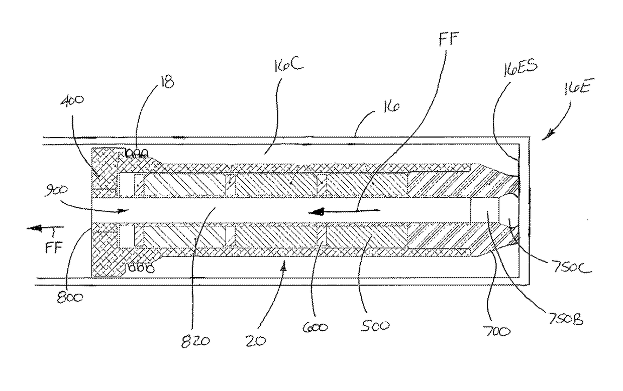
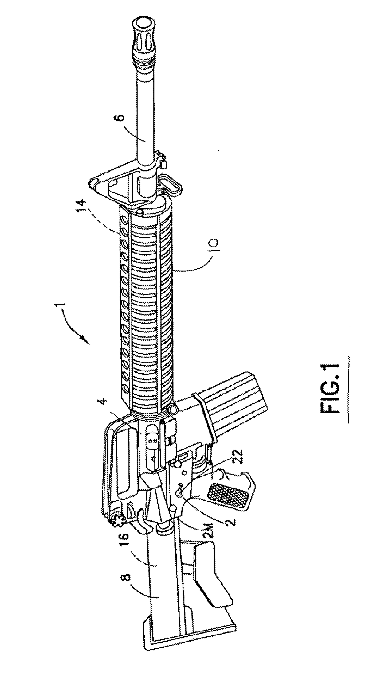
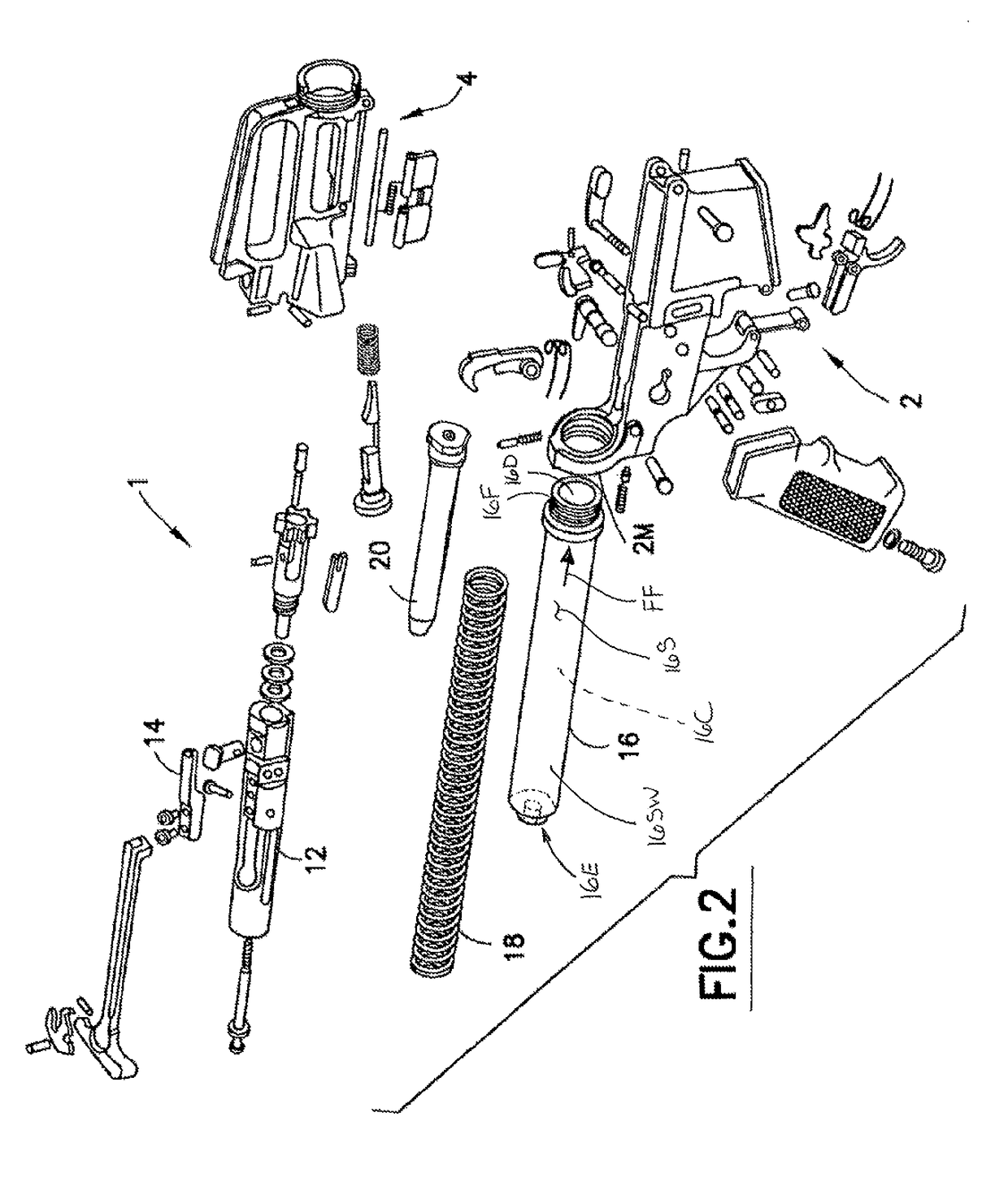
[0016]Referring to FIGS. 1 and 2, there is respectively shown a perspective view of a firearm 1 including aspects of the disclosed embodiment, and an expanded view of portions of the firearm 1. In one aspect, the firearm 1 is illustrated as generally having a black rifle configuration. The black rifle configuration being the family of rifles developed by Eugene Stoner, for example, such as an M4, M15 / M16 type automatic (or semiautomatic or selective fire) firearm configuration having calibers ranging from 0.177 inches to 0.5 inches (e.g. 50 cal.). However, the features of the aspects of the disclosed embodiment, as will be described below, are equally applicable to any desired type of automatic, semiautomatic and / or selective fire firearm having any suitable caliber. Firearm 1 may have operational features such as described in U.S. Pat. Nos. 5,726,377, 5,760,328, 4,658,702 and 4,433,610, and U.S. patent application Ser. No. 10 / 836,443, filed Apr. 30, 2004 and U.S. Provisional Patent...


PUM


Abstract

A black rifle including a receiver with a bolt carrier movably located therein, a receiver extension tube connected to the receiver, the receiver extension tube including an aperture disposed at an end of the receiver extension tube, and a buffer assembly having an interface surface configured to interface with bolt carrier and being configured to reciprocate through the aperture within the receiver extension tube, the buffer assembly including an open fluid passage, through the buffer assembly, that is sized and shaped for enabling movement of the bolt carrier relative to the receiver and effect automatic or semi-automatic fire when the receiver extension is at least partially filled with water.

Description

CROSS REFERENCE TO RELATED APPLICATIONS[0001]This application is a non-provisional of and claims the benefit of U.S. provisional patent application No. 62 / 239,602 filed on Oct. 9, 2015 the disclosure of which is incorporated herein by reference in its entirety.BACKGROUND1. Field[0002]The aspects of the disclosed embodiment described herein relate to automatic or semi-automatic firearms and, more particularly, to automatic and semi-automatic firearms employable in “over the beach” operations.2. Brief Description of Related Developments[0003]The AR15 / M16 family of weapons and their derivatives including the M-4 and indirect gas operated versions, have been in use by the military, law enforcement and civilian population for many years. In law enforcement and military applications in particular, the AR15 / M16 family of weapons may be deployed from or in a marine (salt or fresh water) environment where the weapon may be submerged or subjected to water splashing on or entering the weapon. ...

Claims


Application Information

Patent Timeline
Patent Type & Authority Patents(United States)
IPC IPC(8): F41A3/84
CPCF41A3/84
Inventor PAWLOWSKI, CASIMIR
Owner TCC SOLUTIONS
Why Eureka
Try Eureka