Lighting control device, lighting control system, lighting control method, and non-transitory computer-readable recording medium

a lighting control device and control system technology, applied in the direction of energy-efficient lighting, sustainable buildings, semiconductor lamp usage, etc., can solve the problems of burdening tasks and user burdens, and achieve the effect of burdening users with operating the lighting control devi

Active Publication Date: 2018-08-21
PANASONIC INTELLECTUAL PROPERTY MANAGEMENT CO LTD
View PDF13 Cites 2 Cited by
  • Summary
  • Abstract
  • Description
  • Claims
  • Application Information

AI Technical Summary

Benefits of technology

[0009]According to the present disclosure, burdens placed on a user associated with operating a lighting

Problems solved by technology

In short, the tasks required of the user in order to perform a desired control are burdening.
It is

Method used


Image

  • Lighting control device, lighting control system, lighting control method, and non-transitory computer-readable recording medium
  • Lighting control device, lighting control system, lighting control method, and non-transitory computer-readable recording medium
  • Lighting control device, lighting control system, lighting control method, and non-transitory computer-readable recording medium

Examples


embodiment 1

[0025]Hereinafter, lighting control system 10 including a lighting control device according to one embodiment of the present disclosure will be described.

[0026]Lighting control system 10 is a system for controlling a plurality of luminaires (e.g., scheduling relating to lighting, adjustment of dimming level, etc.) located in a plurality of spatial locations, examples of which include floors and rooms of a building, such as a commercial building. This embodiment will describe lighting control system 10 that controls luminaires located in a plurality of rooms of a building without greatly burdening the user.

(1-1. Configuration of Lighting Control System 10)

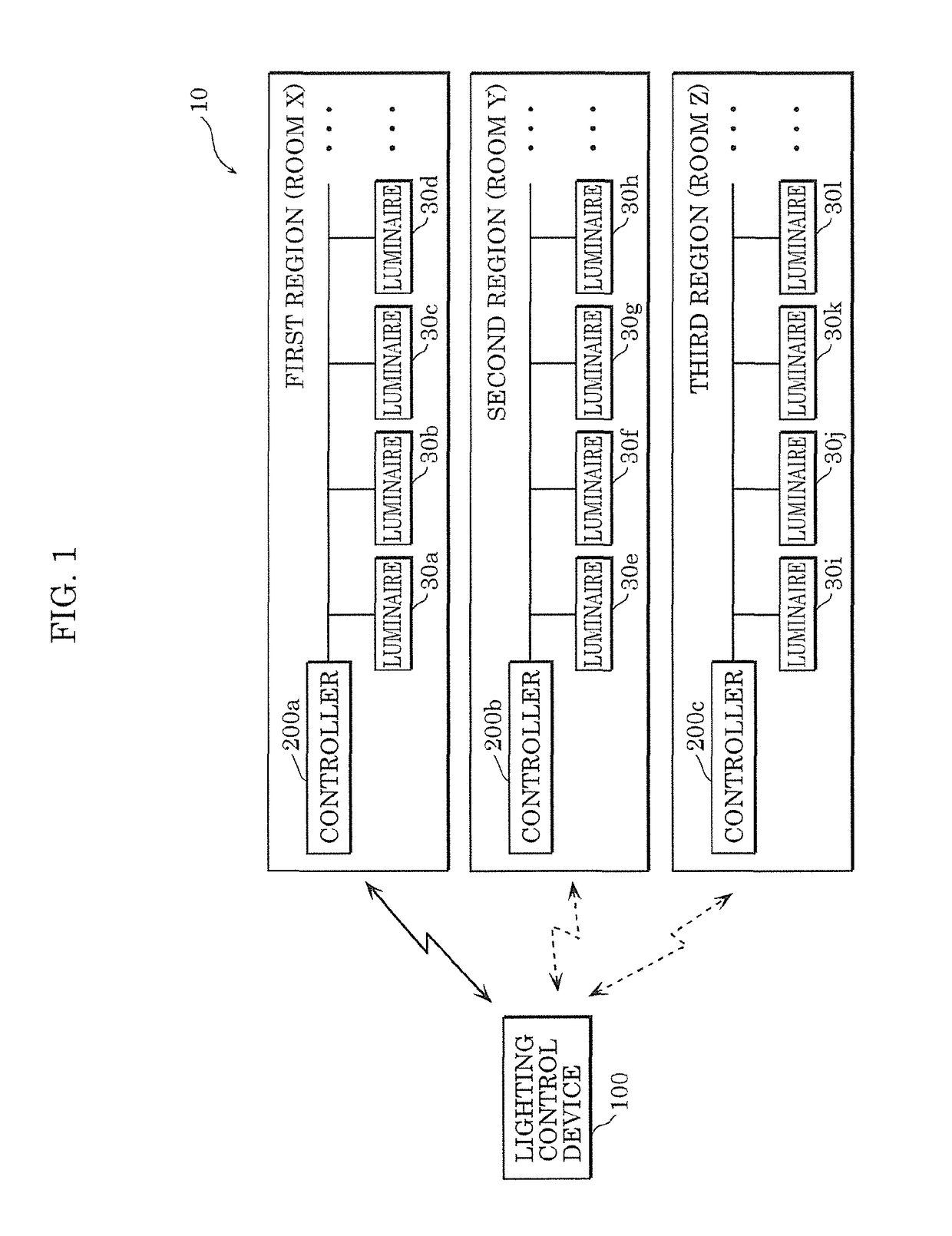
[0027]FIG. 1 illustrates an outline of the configuration of lighting control system 10 according to this embodiment.

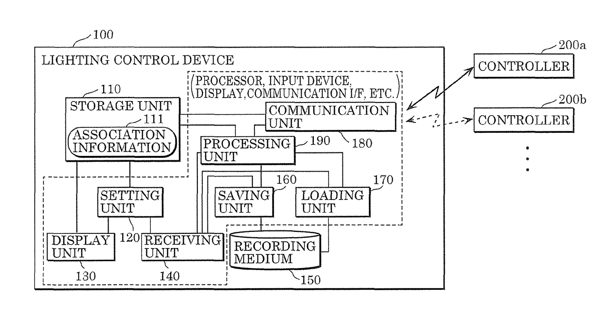
[0028]As illustrated in FIG. 1, lighting control system 10 includes luminaires 30a through 30l located in a plurality of rooms (locations), controllers 200a through 200c each of which is located in different one of the...

embodiment 2

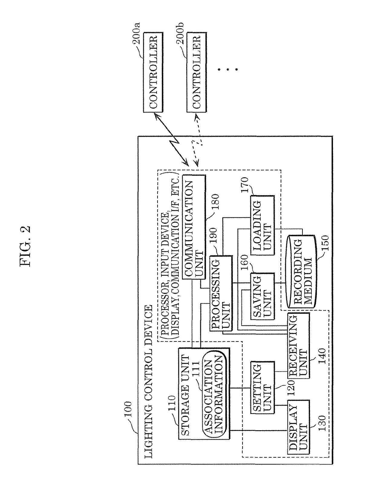
[0069]Hereinafter, an embodiment in which part of lighting control device 100 in lighting control system 10 exemplified in Embodiment 1 has been changed will be described.

(2-1. Variation of Lighting Control System 10 and Usage Example)

[0070]Lighting control device 100 according to Embodiment 1 may or may not perform user authentication. In contrast, the lighting control device according to this embodiment performs user authentication, and can execute a function for controlling luminaires only after the user authentication is successful. Except for the inclusion of lighting control device 100a, which is a variation of lighting control device 100, the lighting control system according to this embodiment is the same as lighting control system 10 illustrated in FIG. 1 and as such, the same reference signs as in FIG. 1 are used.

[0071]In this embodiment, the first location (room X), second location (room Y), and third location (room Z) illustrated in FIG. 1 will be exemplified as location...


PUM


Abstract

A lighting control device is provided that controls luminaires in respective rooms via respective controllers. The lighting control device includes: a storage unit that stores association information in which names (e.g., room names) are associated with SSIDs of the controllers; a communication unit that connects to and transmits and receives information to and from one of the controllers; a display unit that displays names included in the association information in a manner to be selectable; a receiving unit that receives an input from a user including a selection input of a name selected from the names displayed; and a processing unit that, when the receiving unit receives the selection input of the name, executes a predetermined process relating to wireless connection with one of the controllers using the SSID associated in the association information with the name specified by the selection input.

Description

CROSS REFERENCE TO RELATED APPLICATION[0001]This application claims the benefit of priority of Japanese Patent Application Number 2017-032684 filed on Feb. 23, 2017, the entire content of which is hereby incorporated by reference.BACKGROUND1. Technical Field[0002]The present disclosure relates to a lighting control system for performing control relating to lighting, a lighting control device used in the lighting control system, and a non-transitory computer-readable recording medium.2. Description of the Related Art[0003]Conventionally, a system that performs control related to, for example, the dimming level (e.g., brightness) of a plurality of luminaires and scheduling for a plurality of luminaires (e.g., timing of turning on and off the luminaires) is known. The lighting management system disclosed in Japanese Unexamined Patent Application Publication (Translation of PCT Application) No. 2012-514829 performs lighting control based on schemata, such as lighting control parameters ...

Claims


Application Information

Patent Timeline
IPC IPC(8): H05B39/04H05B37/02H05B33/08H05B44/00
CPCH05B37/02H05B33/0845H05B47/19H05B47/165Y02B20/00Y02B20/30
Inventor HIDAKA, YUTO
Owner PANASONIC INTELLECTUAL PROPERTY MANAGEMENT CO LTD
Why Eureka
Try Eureka