Steerable catheter

a catheter and catheter technology, applied in the field of catheter systems and methods, can solve the problems of large outer diameters, large reusable and expensive resources of endoscopes and endoscopic equipment systems, and inability to move, etc., and achieve the effects of low cost, high accuracy, and simple us

Active Publication Date: 2018-08-28
SANOVAS
View PDF44 Cites 2 Cited by
  • Summary
  • Abstract
  • Description
  • Claims
  • Application Information

AI Technical Summary

Benefits of technology

[0014]Accordingly, it is an object of the invention to provide a simple to use, lightweight, low cost, highly accurate, steerable catheter system where the catheter can be introduced into the body under direct and / or indirect visualization and can be made portable and disposable.
[0015]It is another object of the invention to provide a steerable catheter that serves to eliminate the need to use large wires and complicated mechanical structures to articulate the distal tip of a catheter.
[0016]It is a further object of the present invention to provide a steerable catheter having a distal end that is able to bend in as many degrees and planes as possible so that the catheter can be maneuvered through very tight turns within the body, such as airway passages, vessel bifurcations, lumens, pleural cavities, and spaces within the tubular structures and capsular spaces of the body.
[0017]It is still another object of the present invention to provide a steerable catheter where the maximum bend of the distal end of the catheter can be achieved with minimum pressures and forces.
[0018]It is a further object of the present invention that an imaging device used to help steer the catheter, such as an image fiber or image sensor, may be cleaned as the device is retracted into and extended out of the distal end of the catheter.

Problems solved by technology

Endoscopes and endoscopic systems are, currently, a reusable and expensive resource in a physician's armamentarium.
In addition, the endoscopic equipment systems required to operate endoscopes are often large, bulky and relatively immobile devices.
A limitation in the utility of the flexible endoscope is that their outer diameters are often too large, their inner ‘working channel’ diameters are often too small, and their lengths are often inadequate to appropriately diagnose and treat the anatomy and corresponding pathologies found in the far reaches of the body's organs, vessels and spaces.
A further limitation of the utility of the flexible endoscope is that the articulation of the distal tip, and thus, its maneuverability, is accomplished through two or more wires that run along the body of the flexible endoscope.
As such, the maneuverability is limited by the capabilities of the mechanical structures that control the wire.
In addition, optimizing the external and internal diameters of the flexible endoscope is limited by the size and requirements of the wires and their associated mechanical structures.
Additionally, complications sometimes arise when a flexible endoscope malfunctions and it becomes difficult to remove the flexible endoscope from the body.
Moreover, in these methods, the articulation of the distal tip is not independent of the body location and the catheter does not have specific controls at the proximal end to sufficiently control or modify the articulation at the distal tip.
Consequently, the navigation and maneuverability of catheters requires great skill, relegating their utility and functionality to the experience and competence of the user.
However, this particular device and method suffers from a number of disadvantages and shortcomings.
Further, the distal steering tip is limited to bending in the axial plane.
Thus, it is unclear whether the distal tip of Miles has suitable elasticity and Young's modulus to achieve maximum bend of the distal tip without deformation or fatigue, or whether it has suitable memory to regain and maintain the steerable catheter's elongation and linear rigidity after bending the distal tip and after repetitive bending of the distal tip.
It is also unclear if the tip is capable of tight turns of up to 150 degrees.
A further disadvantage of both of the above steerable catheters is that, when an imaging device is employed to help steer the catheter, such as an image fiber or image sensor, there is no mechanism for cleaning the device when it is retracted into the catheter after having been extended out into the bodily cavity.

Method used


Image

  • Steerable catheter
  • Steerable catheter
  • Steerable catheter

Examples


Embodiment Construction

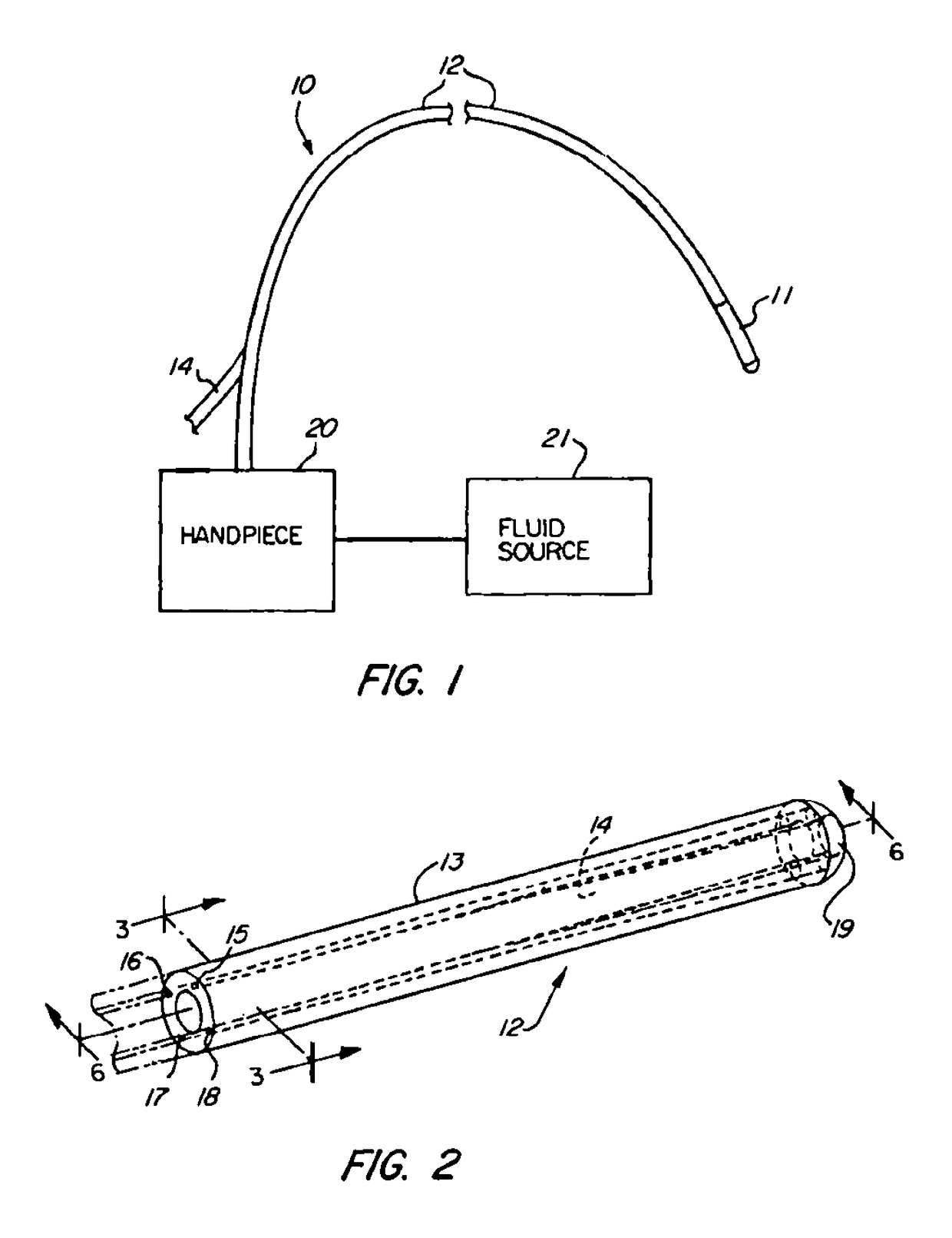
[0048]The basic components of one embodiment of a steerable catheter in accordance with the invention are illustrated in FIG. 1. As used in the description, the terms “top,”“bottom,”“above,”“below,”“over,”“under,”“above,”“beneath,”“on top,”“underneath,”“up,”“down,”“upper,”“lower,”“front,”“rear,”“back,”“forward” and “backward” refer to the objects referenced when in the orientation illustrated in the drawings, which orientation is not necessary for achieving the objects of the invention.

[0049]As shown in FIG. 1, a steerable catheter, generally indicated at reference character (10), includes an elongated catheter body (12) having an elastomeric catheter tip (11) at the distal end, commonly referred to as the distal tip. The catheter (10) is connected to a fluid source (21), which supplies fluid to the catheter body (12), and ultimately, the distal tip (11), via steering lumens disposed therein, as further described below.

[0050]The fluid supplied to the steering lumens may be gas or li...


PUM


Abstract

The present invention relates to a steerable catheter device and method of using the same comprising a catheter body having a distal section. The distal section of the catheter body has an inner lumen, and one or more steering lumen radially offset from the inner lumen. The steering lumen comprise a first end having a first diameter and a second end having a second diameter smaller than the first diameter. A fluid source is in fluid communication with the steering lumen for supplying fluid thereto to radially distend the first end of the steering lumen such that the catheter body bends away from the steering lumen. In some cases, a vacuum is supplied to an opposite lumen to further assist bending of the catheter body. The inner lumen may include a porous material that is utilized to clean an instrument, such as an imaging device, movably disposed in the inner lumen.

Description

FIELD OF THE INVENTION[0001]The present invention relates to systems and methods for moving a catheter in bodily cavities. More specifically, the present invention relates to a catheter having at least one lumen that expands and / or contracts when at least one of pressure and vacuum is / are applied, which allows the catheter to be steered.BACKGROUND OF THE INVENTION[0002]In general, catheters are used in medical procedures in which tubular structures, lumens, pleural cavities or spaces of the body, such as airways, vessels, organs and joints, are diagnostically examined and / or therapeutically treated. Catheters, which can be introduced into the body through a natural orifice or through an incision, can deliver imaging devices, surgical instruments, implants, fluids, drugs, pharmacologic materials, biologic materials, biologic agents and therapeutics to treat or remedy various pathologies found therein. Catheters also guide and deliver other components, such as guide wires, scaffolds a...

Claims


Application Information

Patent Timeline
Patent Type & Authority Patents(United States)
IPC IPC(8): A61B1/005A61M25/092A61B1/015A61M25/01A61M25/00A61B1/00
CPCA61B1/00154A61B1/0057A61B1/015A61M25/0155A61M25/0023A61M25/0026A61M25/0052A61M25/0053A61M25/0054A61M2025/0024A61M2025/0059A61B1/00039A61M25/001A61M25/005A61M25/0012A61M25/0013A61B1/00042
Inventor GUNDAY, ERHAN H.GERRANS, LAWRENCE J.
Owner SANOVAS
Why Eureka
Try Eureka