Tool holder

a tool and tool technology, applied in the field of tool holders, can solve the problems of inability to reliably avoid breakage, reduced rigidity and strength, and high cost, and achieve the effects of reducing production cost, facilitating cooling of cutting edges, and reducing labor intensity

Active Publication Date: 2018-08-28
FRANZ HAIMER MASCHINENBAU KG
View PDF43 Cites 2 Cited by
  • Summary
  • Abstract
  • Description
  • Claims
  • Application Information

AI Technical Summary

Benefits of technology

[0003]One aspect of the invention relates to an economical and easily producible tool holder and a tool arrangement with such a tool holder that enables cooling of the cutting edges of the rotary tool without great production effort and expense.

Problems solved by technology

Particularly for smaller tool holders with smaller diameters of the holding pin, the rigidity and strength is additionally reduced by these coolant and / or lubricant channels, and therefore breakage cannot be reliably avoided.
Angled bores must be introduced into the holding pin in order to produce these channels, which is extremely expensive.
Furthermore, the hardening of the holding pin, which is usually necessary, is hampered by the small wall thicknesses in the coolant bore area, since stress cracks can easily form.

Method used


Image

  • Tool holder
  • Tool holder
  • Tool holder

Examples


Embodiment Construction

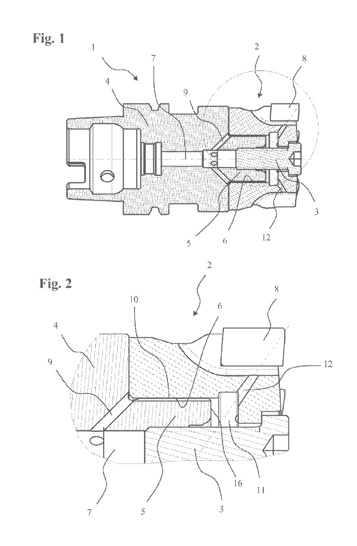
[0028]FIG. 1 shows a tool holder 1, on which a rotary tool 2 is mounted by means of a clamping bolt 3. The tool holder 1 consists of a main body 4, at the front, tool-side end of which a holding pin 5 is arranged. The rotary tool 2 is constructed as a cutting head and has a holding bore 6 corresponding to the holding pin 5, such that the rotary tool 2 can be pushed onto the tool holder 1 and is retained and centered radially by the holding pin 5.

[0029]At the side of the tool holder 1 facing away from the rotary tool 2, clamping faces in the form of a positive taper lock interface for mounting the tool holder 1 in a spindle (not shown) of a machine tool are formed. Coolant and / or lubricant is conducted via a central cooling bore 7 from the spindle to the cutting edges 8 of the cutting head 2. Starting from the central cooling bore 7, channels in the form of radial bores 9 are provided, which open at the outer circumference of the holding pin 5 at the transition of the holding pin 5 i...


PUM


Abstract

A tool holder has a main body and a holding pin onto which a rotary tool having a corresponding holding bore can be placed. At least one channel for transporting coolant or lubricant, the channel leading to the outer circumference of the holding pin, is arranged in the tool holder. In order to enable cooling of the cutting edges of the rotary tool without great production complexity, at least one longitudinal groove for conducting the coolant or lubricant in a longitudinal direction of the holding pin is arranged on the outer circumference of the holding pin.

Description

FIELD OF THE INVENTION[0001]The invention relates to a tool holder, and to a tool arrangement.BACKGROUND OF THE INVENTION[0002]A tool holder of the type in question is known from DE 40 19 506 A1. It has a main body and a holding pin onto which a rotary tool constructed as a cutting head and having a corresponding holding bore can be placed. A channel for transporting a coolant and / or lubricant and opening at the outer circumference of the holding pin is arranged in the tool holder. The coolant and / or lubricant is then transported to the cutters of the cutting head via a plurality of coolant bores in the cutting head. The rotary tool is mounted by means of a bolt that is screwed at the front end face of the holding pin into a corresponding centrally arranged mating thread in the holding pin, thus tensioning the rotary tool against the tool holder. In order to conduct coolant and / or lubricant to the cutting edges of the rotary tool, at least one channel for the coolant and / or lubrican...

Claims


Application Information

Patent Timeline
Patent Type & Authority Patents(United States)
IPC IPC(8): B23C5/28B23C5/26B23Q11/10B23B31/11B23B31/10
CPCB23Q11/1023B23B31/10B23B31/11B23C5/26B23C5/28B23Q11/10B23B2231/24B23B2250/12B23C2210/02B23C2250/12
Inventor HAIMER, FRANZ
Owner FRANZ HAIMER MASCHINENBAU KG
Why Eureka
Try Eureka