
Measuring apparatus

a technology of measuring apparatus and measuring axis, which is applied in the field of measuring axis, can solve the problems of reducing the measurement accuracy of position and orientation, amplifying the measurement error amount of the shift amount of the light beam, etc., and achieve the effect of improving the accuracy

Active Publication Date: 2018-08-28
CANON KK
View PDF15 Cites 0 Cited by
  • Summary
  • Abstract
  • Description
  • Claims
  • Application Information

AI Technical Summary

Benefits of technology

The present invention is about a device that can measure things more accurately, even when using a part that splits light into different colors. This invention makes it easier to get accurate readings from the colors that are being measured.

Problems solved by technology

An edge detection error occurs in the grayscale image, and the measurement accuracy of the position and orientation lowers.
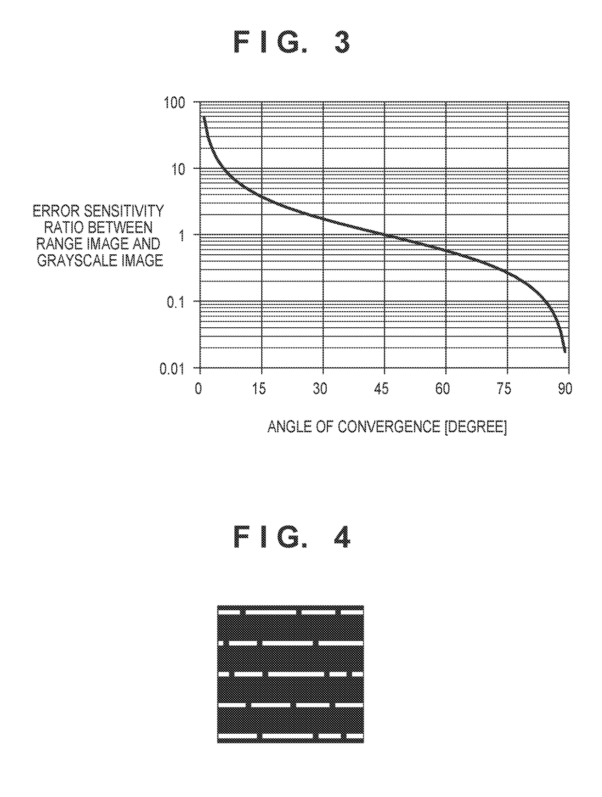
In particular, when the range image is obtained by the principle of triangulation such as a pattern projection method, a measurement error amount associated with the shift amount of the light beam is amplified depending on the condition of the angle of convergence.

Method used


Image

  • Measuring apparatus
  • Measuring apparatus
  • Measuring apparatus

Examples


first embodiment

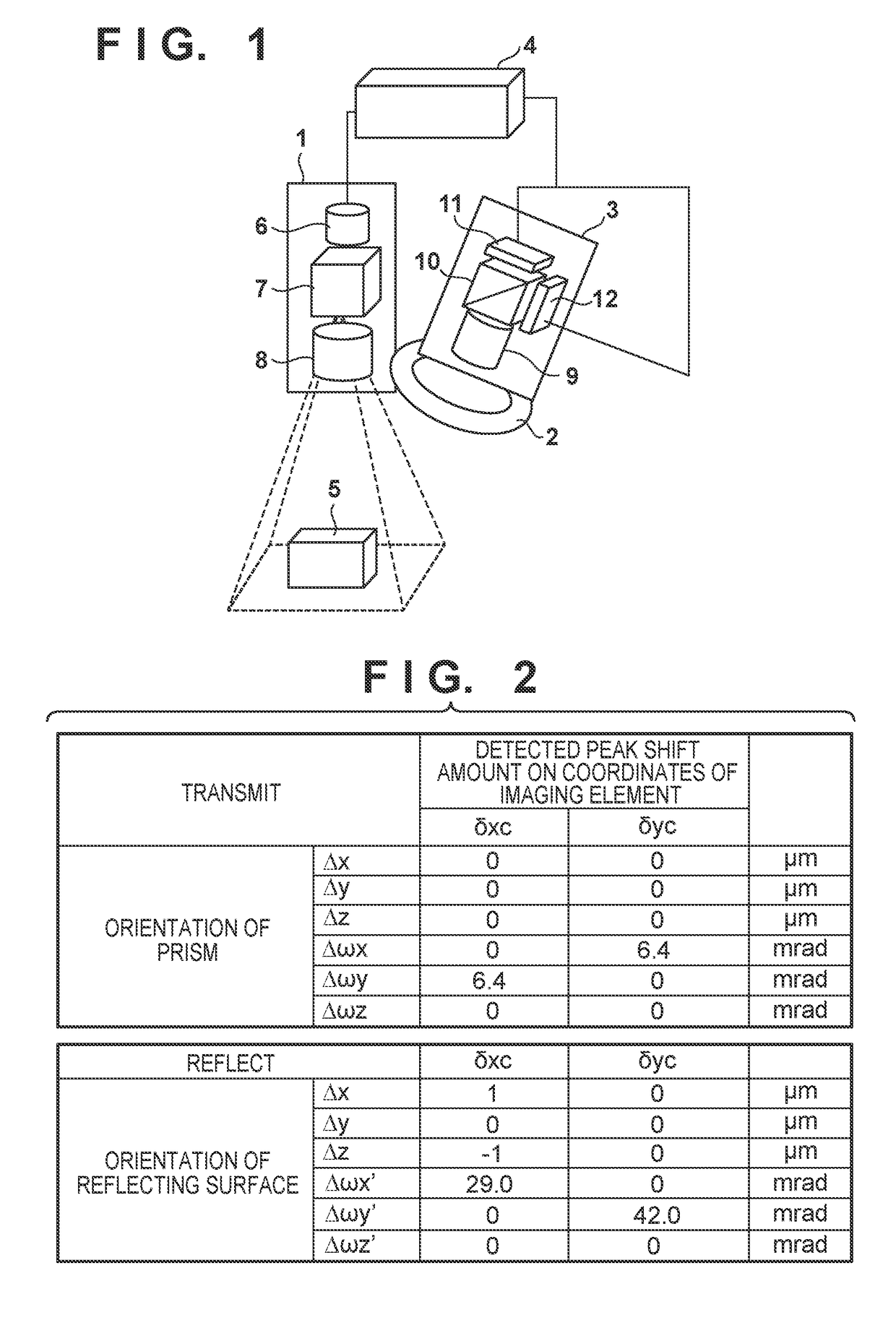
[0019]A measuring apparatus according to the first embodiment, which measures the shape of an object, will be described with reference to FIG. 1. The measuring apparatus according to this embodiment includes a first illumination unit 1 for a range image (first image) representing the three-dimensional shape of an object, a second illumination unit 2 for a grayscale image (second image) representing the contour of an object, an imaging unit 3, and a processor 4. The first illumination unit 1 illuminates an object 5 with pattern light (first light) of a first wavelength. At the same time, the second illumination unit 2 illuminates the object 5 with second light of a second wavelength different from the first wavelength.

[0020]Measurement of the range image will be described first. The range image is obtained by a pattern projection method based on the principle of triangulation, and the three-dimensional shape information of the object 5 is generated as point group data. In this embodi...

second embodiment

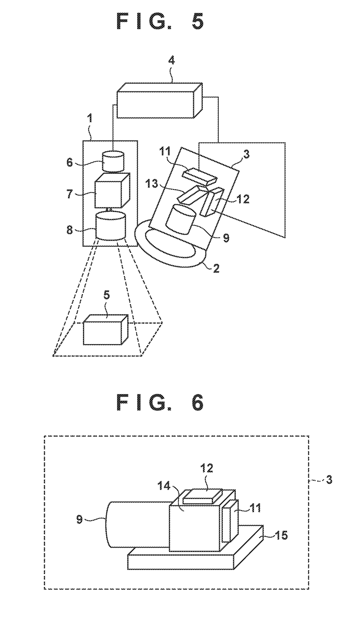
[0029]A measuring apparatus according to the second embodiment will be described with reference to FIG. 5. The measuring apparatus according to the second embodiment includes a first illumination unit 1 for a range image, a second illumination unit 2 for a grayscale image, an imaging unit 3, and a processor 4. A description of parts common to the first embodiment will be omitted.

[0030]The measuring apparatus according to the second embodiment includes a parallel plate dichroic mirror 13 as a wavelength dividing element. In the second embodiment, since the parallel plate wavelength dividing element is used, the rigidity of the wavelength dividing element itself lowers, and the shift of a reflected light beam increases, unlike the prism-shaped wavelength dividing element of the first embodiment. When the parallel plate dichroic mirror 13 is used, the distance to pass a transmitted light beam in the medium is shortened, and therefore, the shift of the transmitted light beam becomes sma...


PUM


Abstract

A measuring apparatus includes an optical system including a wavelength dividing element that divides light from an object simultaneously illuminated by first and second illumination units into a light component of a first wavelength and a light component of a second wavelength. A first imaging element receives a pattern light of the first wavelength reflected by the object, which is light transmitted through the wavelength dividing element but never reflected by the wavelength dividing element, thereby obtaining a first image representing a three-dimensional shape of the object. A second imaging element receives the light of the second wavelength reflected by the object, which is light reflected by the wavelength dividing element, thereby obtaining a second image representing an edge of the object.

Description

BACKGROUND OF THE INVENTION[0001]Field of the Invention[0002]The present invention relates to a measuring apparatus for measuring the shape of an object.[0003]Description of the Related Art[0004]Along with the recent advances of robot technologies, a robot takes on a complex process such as assembly of an industrial product. To implement assembly by the robot, it is necessary to measure the relative positions and orientations between an end effect such as a hand of the robot and a grip target component. A method of measuring the position and orientation of a target component is described in Japanese Patent No. 5393318. In the method described in Japanese Patent No. 5393318, fitting with a model such as CAD is performed using both edge information obtained from a grayscale image and a range image obtained by a three-dimensional measuring method such as a pattern projection method, thereby measuring the position and orientation of a target component.[0005]To obtain the grayscale image...

Claims


Application Information

Patent Timeline
Patent Type & Authority Patents(United States)
IPC IPC(8): G01B11/245G02B27/14G02B27/12G06T7/521
CPCG01B11/245G02B27/126G02B27/141G06T7/521G06T2207/30164G06T2207/10024G06T2207/10152
Inventor HATADA, AKIHIRO
Owner CANON KK
Learn More