Platter supported and driven turntable

a technology of turning tables and turntables, applied in the field of turning tables, can solve the problems of belt oscillation, increased motor noise level coupled into the music, and inability to adjust the speed of the motor,

Active Publication Date: 2018-08-28
HORN CYNTHIA BENNETT +1
View PDF9 Cites 1 Cited by
  • Summary
  • Abstract
  • Description
  • Claims
  • Application Information

AI Technical Summary

Problems solved by technology

However, one downside is that an increased motor noise level is coupled into the music.
One downside is that it couples more motor noise into the music.
This belt has a tendency to oscillate and to stretch slightly during loud musical passages which dulls the musical peaks.
Low mass belt drive turntables suffer from speed instabilities due to needle drag during loud musical passages so as to dull musical transients.
The elastic material has similar problem as the drive belt.
A conventional magnetic coupled platter turntable is expensive.
The strong supporting pillars drain energies from the tonearm energy loop and degrade sound qualities.
It adds noise and distortion to a desired musical signal that the needle supposed to pick up.
The echo effect results in a heavy or dead sound signal.
Not all conventional models of turntables will be suitable for use with the present disclosure.
Some conventional models do not have enough power to drive the platter supported and driven turntable of the present disclosure steadily or up to a proper speed.
Some conventional models do not provide stable support to the platter supported and driven turntable of the present disclosure.

Method used


Image

  • Platter supported and driven turntable
  • Platter supported and driven turntable
  • Platter supported and driven turntable

Examples


Embodiment Construction

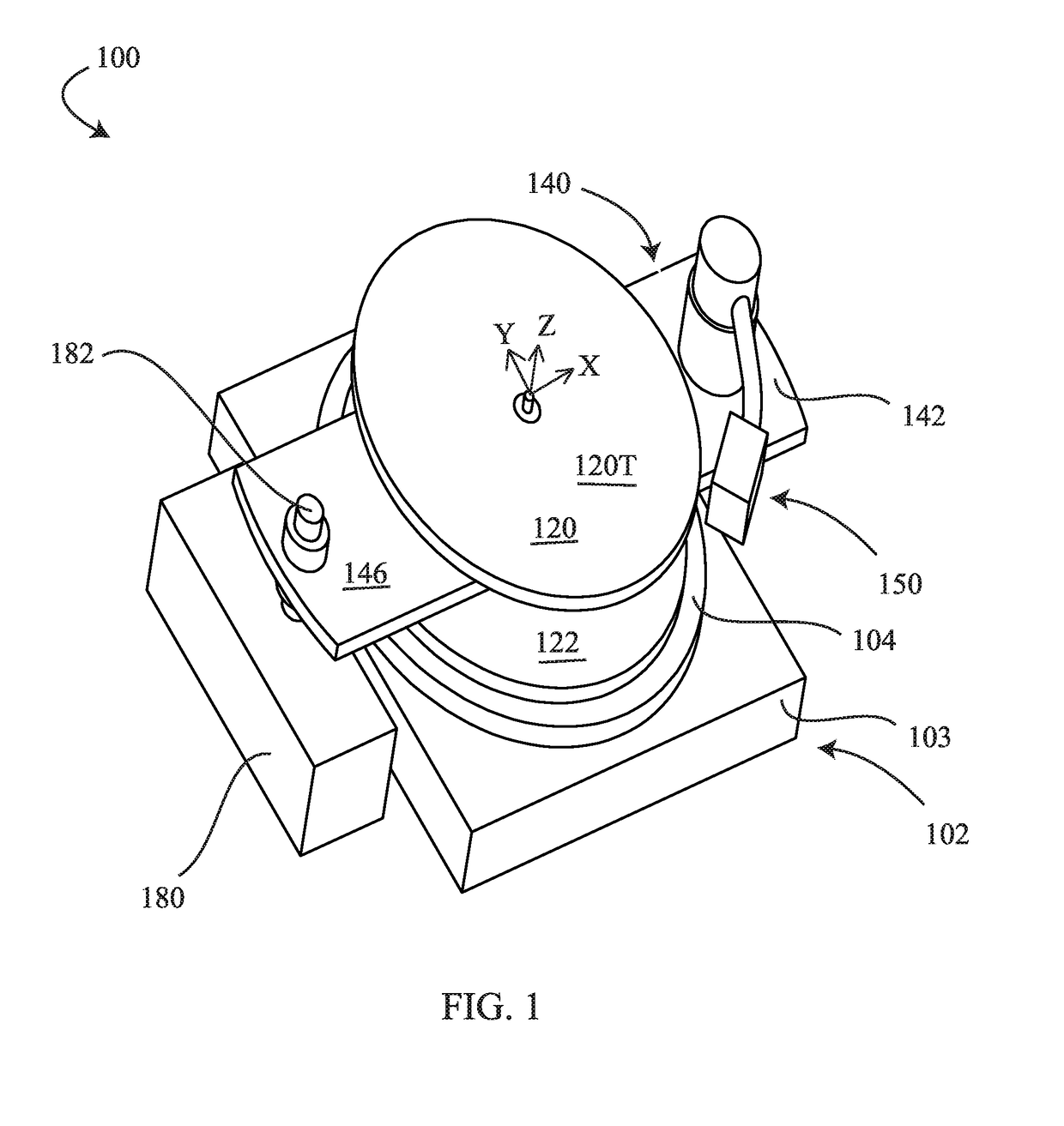
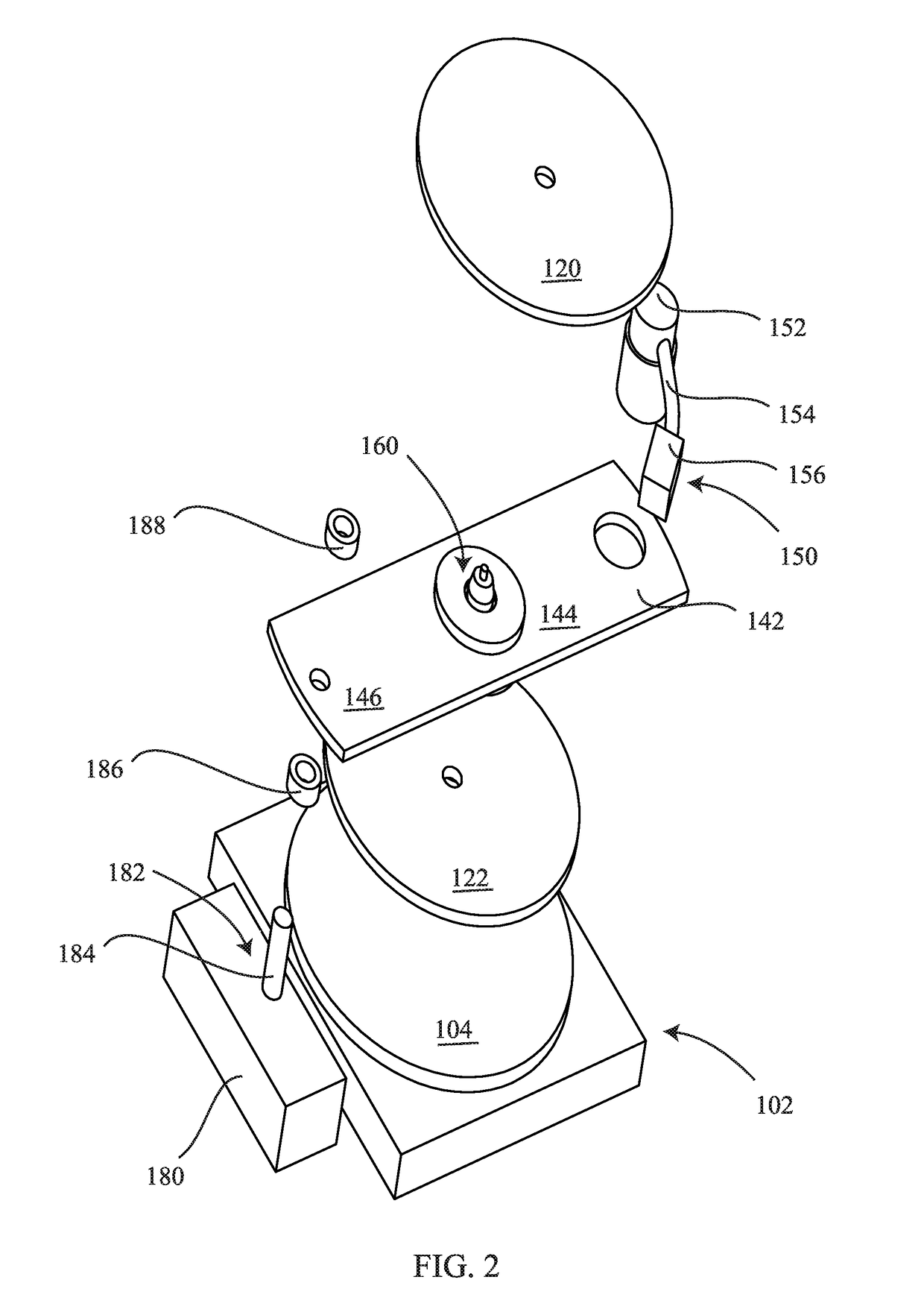
[0047]FIG. 1 is a perspective view of a platter supported and driven turntable 100 mounted on a supporting turntable 102 in examples of the present disclosure. FIG. 2 is an exploded view (exploded along Z-direction of FIG. 1) of the platter supported and driven turntable 100 and the supporting turntable 102 of FIG. 1 in examples of the present disclosure. FIG. 4 is a cross-sectional view (viewing a cross-section at XZ plane from a negative Y location of FIG. 1) of the platter supported and driven turntable 100 and the supporting turntable 102 of FIG. 1 in examples of the present disclosure. In one example, the supporting turntable 102 is an Audio-Technica AT-LP120-USB Direct-Drive turntable. In another example, the supporting turntable 102 is an Audio-Technica AT-LP3BK Fully Automatic Belt-Drive Stereo Turntable.

[0048]Referring now to FIGS. 1, 2 and 4, the platter supported and driven turntable 100 has a spindle 160, an upper circular platter 120, a lower circular platter 122 (also ...


PUM

PropertyMeasurementUnit
weightaaaaaaaaaa
heightaaaaaaaaaa
rectangular shapeaaaaaaaaaa

Abstract

A platter supported and driven turntable has a spindle, an upper circular platter, a lower circular platter, an arm board, and a tonearm assembly. The spindle is to rotate about a first direction. The spindle has a hub, a shaft and a bearing assembly between the hub and the shaft. The shaft has a flange. The upper circular platter is attached to the shaft of the spindle. The lower circular platter is attached to the flange of the shaft of the spindle. The arm board is attached to the hub of the spindle. The arm board has a first extension section, a mid-range section, and a second extension section. The mid-range section of the arm board is disposed between the upper circular platter and the lower circular platter. The tonearm assembly is directly attached to the first extension section of the arm board. The second extension section of the arm board is attached to a ballast or a supporting turntable through one or more adjustable height mounts.

Description

CROSS-REFERENCE TO RELATED APPLICATIONS[0001]This patent application claims benefit of a provisional patent application 62 / 529,118 having a Filing Date of Jul. 6, 2017. The disclosure made in the provisional patent application 62 / 529,118 is hereby incorporated by reference.FIELD OF THE INVENTION[0002]This invention relates generally to a turntable for playing a record. More particularly, the present invention relates to a platter supported and driven turntable configured to be mounted on a supporting turntable.BACKGROUND OF THE INVENTION[0003]Turntables are also called phonographs or record players. Turntables may be characterized into different types. Three most common types of conventional turntables include direct drive type turntable, idler drive type turntable and belt drive type turntable. In examples of the present disclosure, applicant's test results show that the present disclosure significantly improves sound quality of the direct drive type turntable; improves sound quali...

Claims


Application Information

Patent Timeline
Patent Type & Authority Patents(United States)
IPC IPC(8): G11B3/60G11B3/14G11B19/20G11B33/08
CPCG11B3/14G11B3/60G11B19/20G11B33/08G11B3/61G11B3/12G11B19/2018
Inventor HORN, CYNTHIA BENNETTWILLS, THEODORE S.
Owner HORN CYNTHIA BENNETT
Why Eureka
Try Eureka