
Phonograph tone arm mounting, decoupling, vertical tracking angle adjustment system, and vertical guide system

a technology of vertical tracking angle adjustment and phonograph, which is applied in the direction of instruments, head support, data recording, etc., can solve the problems of creating too much force and friction

Inactive Publication Date: 2007-01-11
RIGGLE PETER
View PDF15 Cites 6 Cited by
  • Summary
  • Abstract
  • Description
  • Claims
  • Application Information

AI Technical Summary

Benefits of technology

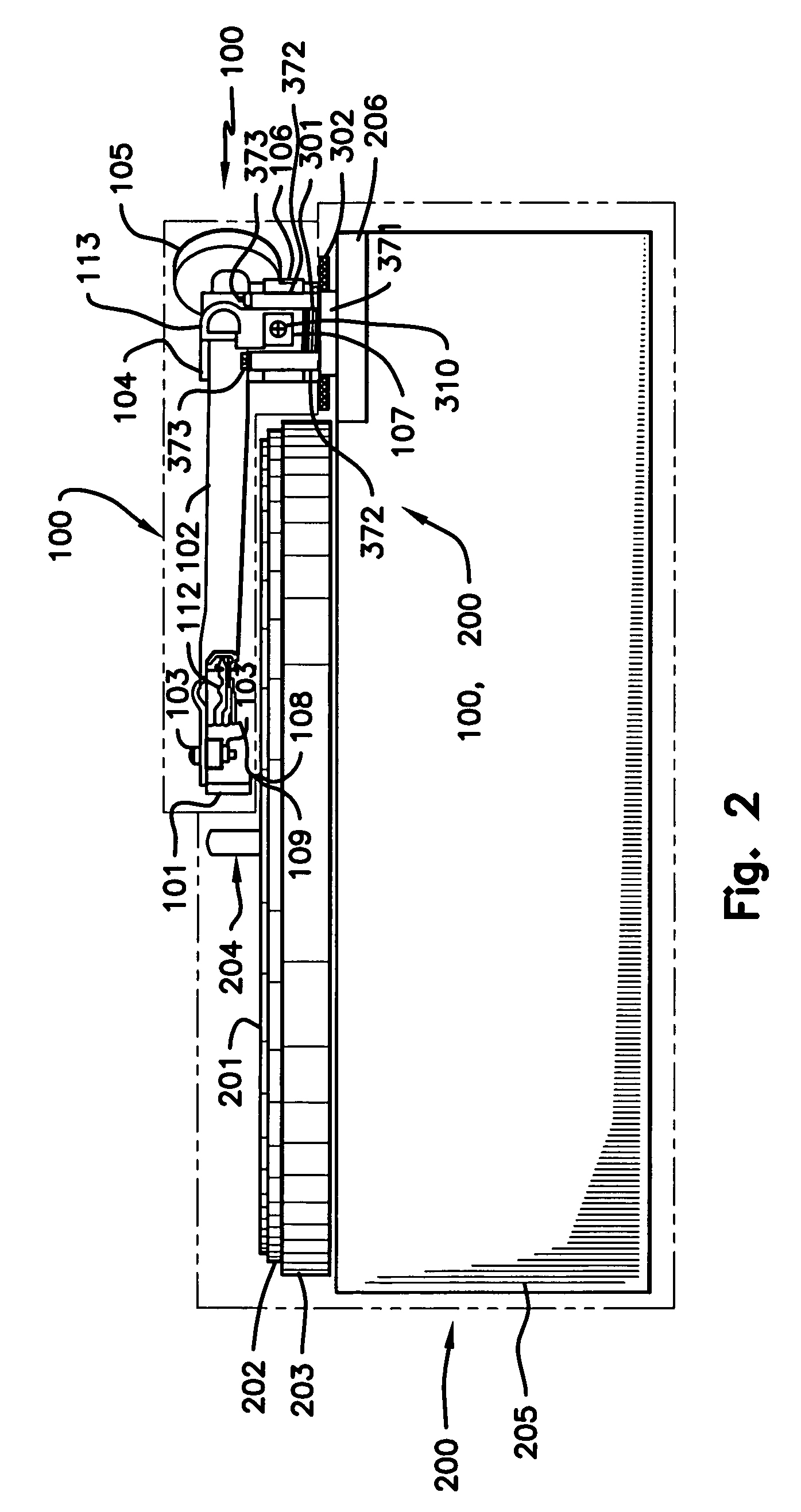
[0029] Adjuster wheel (302) provides easy adjustment of VTA (110), and thereby the important SRA (111), by changing the height of tone arm pedestal (106), with or without phonograph record (201) in play. Adjuster wheel (302) is located directly below tone arm pedestal (106) and runs on adjuster screw external threads (312). Adjuster screw (301) is affixed to and extends vertically downward from tone arm pedestal bottom (114). Adjuster wheel (302) and adjuster screw (301) have a common vertical axis, adjuster screw axis of revolution (309), aligned closely to tone arm system weight center of gravity (310). Adjuster wheel (302) has a substantially larger diameter than tone arm pedestal (106) allowing access to its rim for easy manual operation or mechanical operation using remote control (213)
[0032] b) Tone arm pedestal (106) is held down to arm board (206) by nothing more than the weight of tone arm system (100), thereby minimizing the connecting force between tone arm system (100) and turntable system (200), thereby reducing the transfer of vibration from tone arm system (100) to arm board (206) and back again, and thereby improving the quality of the signal and of the perceived sound.
[0035] The invention (300) eliminates fastening of tone arm pedestal (106) to arm board (206), thereby simplifying tone arm system (100) installation to and removal from arm board (206), at the time of manufacture, during shipping, and in use of turntable system (200) and tone arm system (100) by the end user. With this invention (300), tone arm system (100) may be lifted directly out of and returned to thrust bushing (307) affixed to arm board (206), without breaking or making mechanical fastener connections, and with no access to the bottom of arm board (206) other than to guide the signal leads (112) out of or in to turntable system (200).
[0036] Ease of assembly and disassembly has high value, because a) it is difficult to work on tone arm system (100) and pickup cartridge (101) with tone arm system (100) fixed to turntable system (200), and b) using only the prior art, it is difficult and / or time consuming to assemble and disassemble tone arm system (100) to and from turntable system (200).
[0038] The invention (300) allows the use of a lightly loaded damping washer (306) which serves as a vibration damping and filtering layer between tone arm pedestal (106) and thrust bushing top face (308), or between adjuster wheel (302) thrust bushing top face (308), allowing damping and filtering characteristics to be tailored for best perceived sound.

Problems solved by technology

It was found that the hold-down spring created too much force and friction to allow smooth and easy operation of adjuster wheel (302).

Method used


Image

  • Phonograph tone arm mounting, decoupling, vertical tracking angle adjustment system, and vertical guide system
  • Phonograph tone arm mounting, decoupling, vertical tracking angle adjustment system, and vertical guide system
  • Phonograph tone arm mounting, decoupling, vertical tracking angle adjustment system, and vertical guide system

Examples


Embodiment Construction

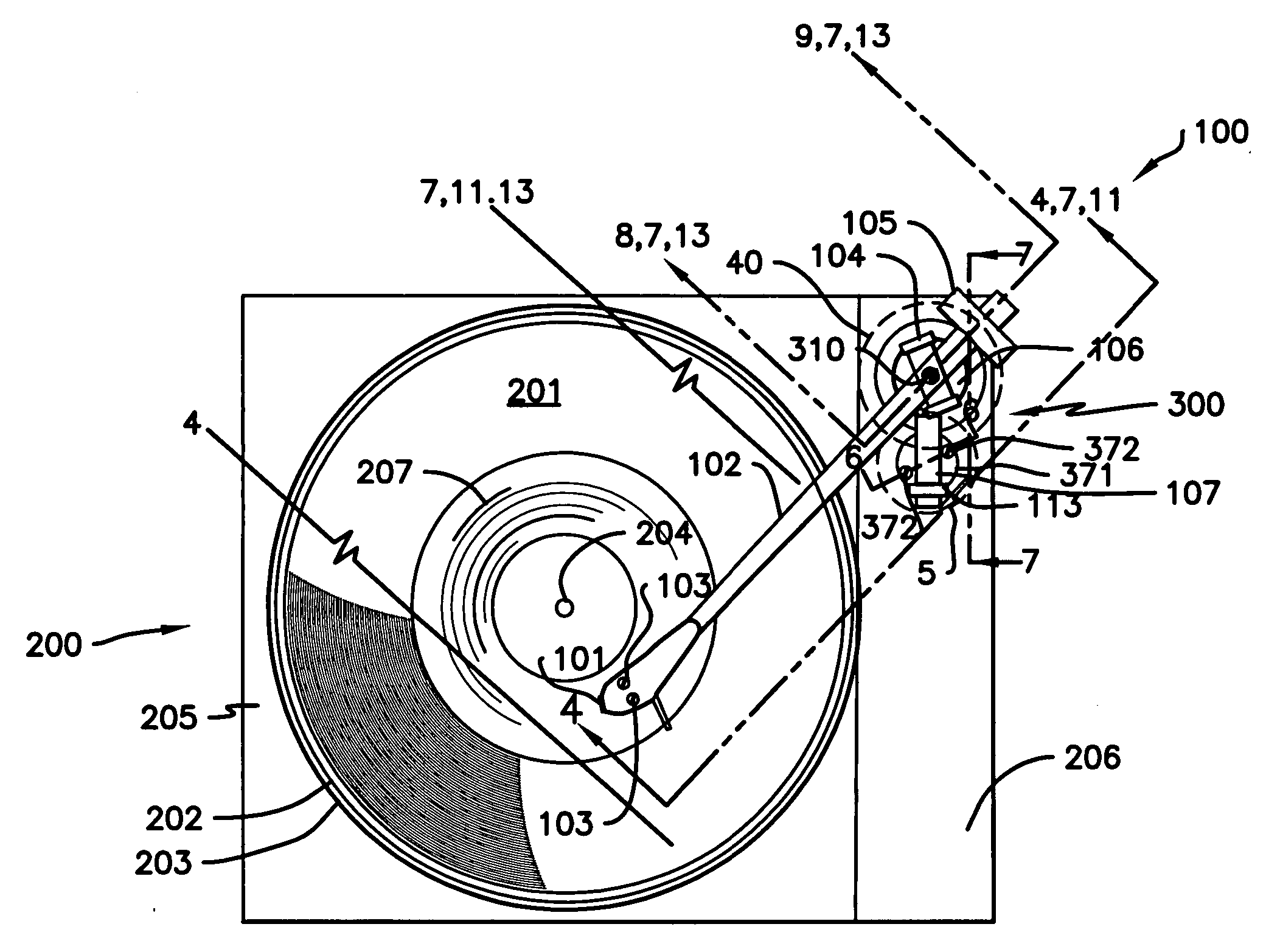
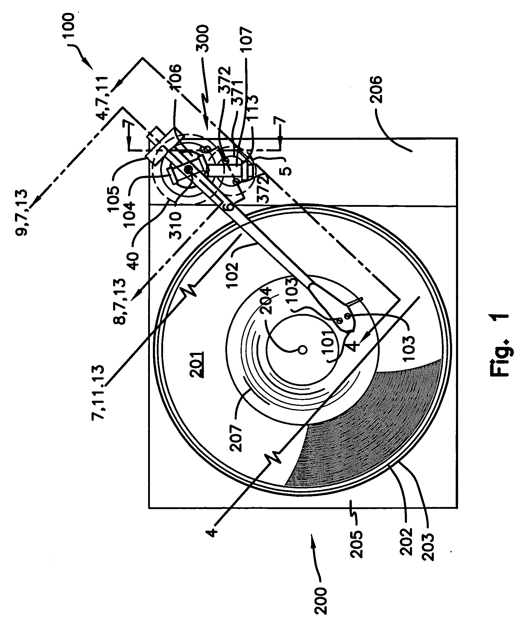
[0058]FIGS. 1, 2, and 3 show tone arm system (100) mounted on turntable system (200) along with components of the invention (300). Dashed lines in FIG. 2 show the approximate boundaries of tone arm system (100) and turntable system (200). The invention (300) serves as an improved system for mounting tone arm system (100) to turntable system (200) with benefits in adjustment of VTA (110), reduction of tone arm system vibration, and improved ease of installation and removal of tone arm system (100) from turntable system (200).

[0059] Regarding tone arm system (100): Pickup cartridge (101) is attached to tone arm proper (102) by pickup cartridge mounting means (103). Tone arm proper (102) is supported by tone arm pivot (104), which allows tone arm proper (102), and components attached thereto, to rotate with two degrees of freedom, one horizontal and one vertical. Counterweight (105) balances the major portion of the weight of tone arm proper (102) and all components attached thereto, ...


PUM

PropertyMeasurementUnit
weightaaaaaaaaaa
gravityaaaaaaaaaa
diameteraaaaaaaaaa

Abstract

An improved tone arm mounting system, for improved damping of tone arm system (100) vibrations. Tone arm system (100) is supported by tone arm pedestal (106). Adjuster screw (301) is affixed to the bottom of tone arm pedestal (106) so that adjuster screw axis of revolution (309) passes through or near tone arm system weight center of gravity (310). Adjuster screw (301), by threaded means, rotatably receives adjuster wheel (302), which is thin and is large in diameter, for easy access to its outer edge for manual or mechanical operation. Rotation of adjuster wheel (302) on adjuster screw (301) changes the height of tone arm pedestal (106) and thereby changes VTA (110). The tone arm system (100) is supported by arm board (206) without vertical connection to arm board (206) thereby damping mechanical vibrations and improving signal quality. A lightly loaded vibration damping washer (306) can be used between thrust bushing (307) and adjuster wheel (302) to damp or filter transfer of mechanical vibrations from tone arm system (100) to arm board (206) and back into tone arm system (100).

Description

FIELD OF THE INVENTION [0001] Phonographs, tone arms, turntables, tone arm mounting, decoupling, damping, and vertical tracking angle adjustment. BACKGROUND OF THE INVENTION [0002] The basic modern phonograph system uses a flat disk phonograph record with spiral cut grooves. The record is played on a turntable system which spins the phonograph record at constant rotational speed, using a tone arm system mounted on the arm board, plinth, or other structure of the turntable system (hereinafter referred to as the arm board). [0003] The tone arm system configuration in greatest use consists of an arm with a pickup cartridge at one end and a counterweight at the other end, and with a tone arm pivot system (hereinafter referred to as the tone arm pivot) for rotation of the arm with two degrees of freedom, one horizontal, and one vertical. The tone arm pivot is located near the balance point of the pickup cartridge, tone arm proper, and counterweight. The tone arm pivot is supported by a p...

Claims


Application Information

Patent Timeline
Patent Type & Authority Applications(United States)
IPC IPC(8): G11B21/16
CPCG11B3/00G11B3/32G11B3/31G11B3/12
Inventor RIGGLE, PETER
Owner RIGGLE PETER
Learn More