Lever-type connector

a technology of lever and connector, applied in the direction of coupling device connection, coupling parts engagement/disengagement, electrical apparatus, etc., can solve problems such as lever breakag

Inactive Publication Date: 2009-12-01
YAZAKI CORP
View PDF5 Cites 6 Cited by
  • Summary
  • Abstract
  • Description
  • Claims
  • Application Information

AI Technical Summary

Benefits of technology

[0009]By the way, the conventional lever-type connector is structured as described above so that the arm plates 111 are opened while one ends of the arm plates 111 being deflected to the outer sides to fit the engagement pin 123 of the connector housing 120 into the engagement hole 113 of the arm plates 111. In this case, the above-described lever 110 causes the arm plates 111 to be deflected to the outer sides so that the deflection of the arm plates 111 is started from supporting points at which the joint section 150 is connected to the arm plates 111. However, the lever 110 having a smaller size in particular causes a reduced distance from the rotation supporting point (the engagement hole 113) to the joint section 150. This means that an increased load is required to deflect the arm plates 111 to attach the arm plates 111 to the connector housing 120. This makes it difficult to attach the lever to the connector housing, which may cause a breakage of the lever 110.
[0010]In view of the above circumstances, it is an objective of the present invention to provide a lever-type connector by which even a lever having a smaller size can be easily attached to a connector housing with a smaller force to remove the causing factor of the broken lever.
[0013]As described above, at a stage at which the lever is attached to the first connector housing, the link member is not attached to a position close to the rotation supporting point between the arm plates. Thus, the arm plates are easily deflected by a small force to the outer sides with the connection bar away from the rotation supporting point as a supporting point. As a result, the rotation supporting point of the arm plate-side is fitted to the rotation supporting pivot at the outer face of the first connector housing. Thus, even when the lever has a smaller size, the lever can be assembled easily. This prevents the lever from being broken due to the arm plates outwardly opened with an excessively-high force. The link member is attached between the arm plates after the lever is attached to the first connector housing. The arm plates are linked in the final assembled condition at a position close to the rotation supporting point. This prevents the arm plates from being opened, thus improving the rigidity of a part of the lever close to the rotation supporting point. Thus, the lever can be prevented from being unnecessarily deformed when the first connector housing and the second connector housing are fitted to each other by the rotation of the lever. This allows a pair of the connector housings to be securely fitted to each other by a smooth lever operation.
[0015]As described above, the movable element of the fitting sensing switch of the lever fitting-type power supply circuit shutoff apparatus is provided as the link member connecting the pair of arm plates of the lever. This eliminates the need to provide the movable element of the fitting sensing switch at any other spaces. Thus, the lever can have a more compact configuration.
[0017]As described above, the movable element provided as the link member is provided in a slidable manner. The movable element can be fitted to the fixed side of the fitting sensing switch only when the connector housings are appropriately fitted to each other. This prevents a risk of a wrong operation and the power supply circuit can be provided in a conduction state only when a fixed procedure is completed securely.

Problems solved by technology

This makes it difficult to attach the lever to the connector housing, which may cause a breakage of the lever 110.

Method used


Image

  • Lever-type connector
  • Lever-type connector
  • Lever-type connector

Examples


Embodiment Construction

[0028]Hereinafter, embodiments of the present invention will be described with reference to the drawings.

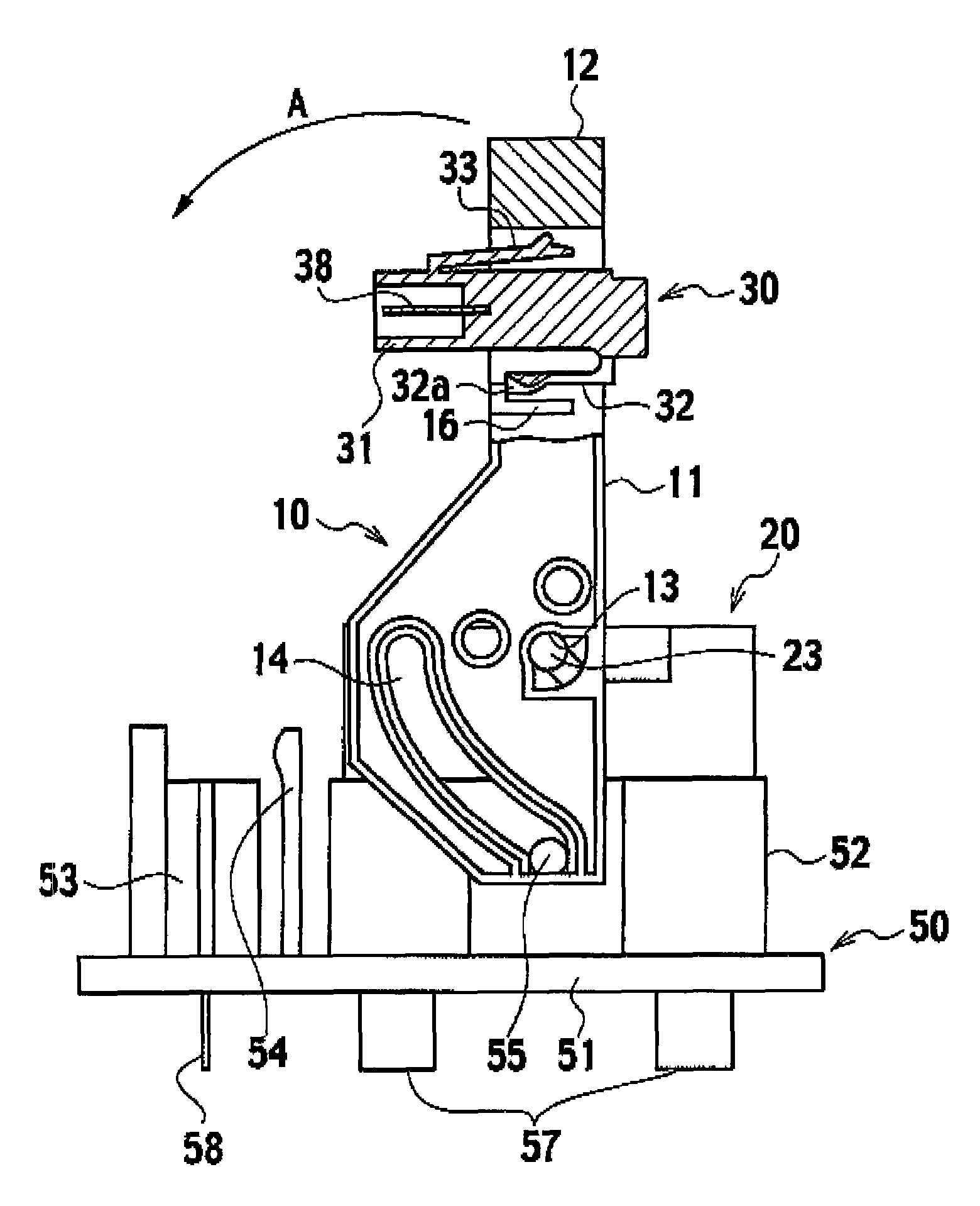
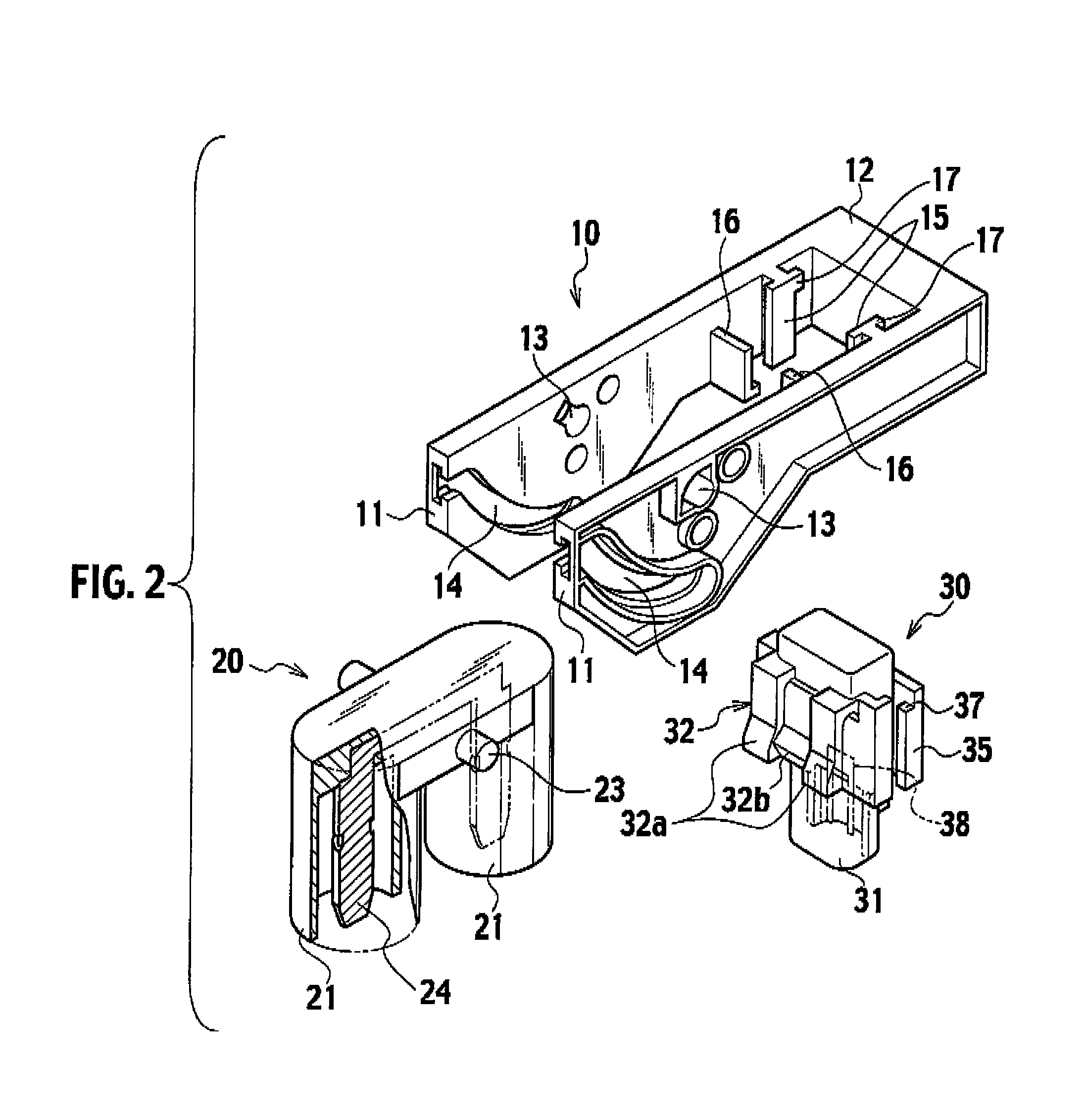
[0029]This lever-type connector is configured as a power supply circuit shutoff apparatus. This lever-type connector includes, as shown in FIG. 4, a pair of connector housings 50 and 20 at the fixed side and the movable side that are both made of synthetic resin and that are fitted to each other; a lever 10 attached to the connector housing 20 of the movable side in an arrow A direction in a rotatable manner; and a movable element 30 of a fitting sensing switch that is attached to the lever 10 after the lever 10 is attached to the connector housing 20.

[0030]The connector housing 50 of the fixed side is structured so that a main connector housing 52 and the fixed-side housing 53 for the fitting sensing switch are provided on a base plate 51. A pair of fixed side power terminals (not shown) constituting a power switch is provided in the main connector housing 52. A pair of fitting ...


PUM


Abstract

A lever is attached to a connector housing in a rotatable manner. This lever includes a pair of arm plates having rotation supporting points at one ends and a connection bar linking the other ends of the arm plates. This lever has a substantially U-like shape. According to this lever, when one ends of the pair of arm plates are opened to the outer sides, the rotation supporting point of the lever is attached, in a rotatable manner, to a rotation supporting pivot of the outer face of the connector housing. By this structure, the lever is rotated for operation to realize a cam action to assist the connectors to be fitted to each other and to be disengaged from one another. According to this lever-type connector, the lever is attached to the connector housing, and subsequently the connection between the arm plates at a position closer to the rotation supporting point of the lever than to the connection bar is provided as a link member linking the arm plates. The movable element of the fitting sensing switch constitutes this link member.

Description

BACKGROUND OF THE INVENTION[0001]1. Field of the Invention[0002]The present invention relates to a lever-type connector used as a power supply circuit shutoff apparatus for example.[0003]2. Description of the Related Art[0004]A lever-type connector as disclosed in Patent Publication 1 has been known as a power supply circuit shutoff apparatus provided in an electric vehicle or the like.[0005]This lever-type connector is structured to rotatably attach a lever to one connector housing of a pair of connector housings fitted to each other. By rotating this lever for operation, an action by a cam mechanism provided between the lever and the other connector housing assists these connector housings to be fitted to each other and to be disengaged from each other.[0006]FIG. 1 shows the structure of the movable side of the similar lever-type connector. A lever 110 includes: a pair of left and right arm plates 111; a grooved engagement hole 113 that is provided at one end of the pair of left a...

Claims


Application Information

Patent Timeline
Patent Type & Authority Patents(United States)
IPC IPC(8): H01R13/62
CPCH01R13/62938H01R13/62955H01R13/6295
Inventor MORI, SHIGEOOHIKE, TERUHIKO
Owner YAZAKI CORP
Why Eureka
Try Eureka