Connector

a technology of connecting parts and components, applied in the direction of coupling device details, coupling device connections, three-pole connections, etc., can solve the problems of increasing the number of components and bolting operations, enlarge the housing, and the inability to visually confirm the connection of the tip side terminal through the work opening, so as to reduce the number of fastening components and fastening components, the effect of ensuring the visual appearance of the fastening operation

Active Publication Date: 2018-08-28
SUMITOMO WIRING SYST LTD
View PDF83 Cites 21 Cited by
  • Summary
  • Abstract
  • Description
  • Claims
  • Application Information

AI Technical Summary

Benefits of technology

[0005]According to this configuration, the terminal and the intermediate terminal can be connected and the intermediate terminal and the mating terminal can be connected only by fastening the fastening component and the fastened component. Further, the fastening component can be fastened to the fastened component while a center position of the fastened component is confirmed through the intermediate terminal. A collar may be used as an example of such an intermediate terminal. That is, the terminal and the mating terminal can be conductively connected via the intermediate terminal. Thus, fastening can be performed at one position while the visibility of a fastening operation is ensured. The number of the fastening components and the fastened components can be reduced as compared to the case where fastening is performed at two positions, and the fastening operation can be reduced.
[0016]According to the connector disclosed by this specification, fastening can be performed at one position while the visibility of a fastening operation is ensured. The number of fastening components and fastened components can be reduced as compared to the case where fastening is performed at two positions, and the fastening operation can be reduced.

Problems solved by technology

In the above shield connector, since a connected part of the connecting piece of the tip side terminal and the base-end side terminal are hidden below the housing, it is not possible to visually confirm through the work opening whether the connecting piece of the tip side terminal and the base-end side terminal are properly connected.
However, in this case, bolting is performed at two positions, thereby increasing the number of components and increasing bolting operations.
Further, since a tool space for performing bolting needs to be provided for two positions, the work opening becomes larger, leading to the enlargement of the housing.

Method used


Image

  • Connector
  • Connector
  • Connector

Examples


Embodiment Construction

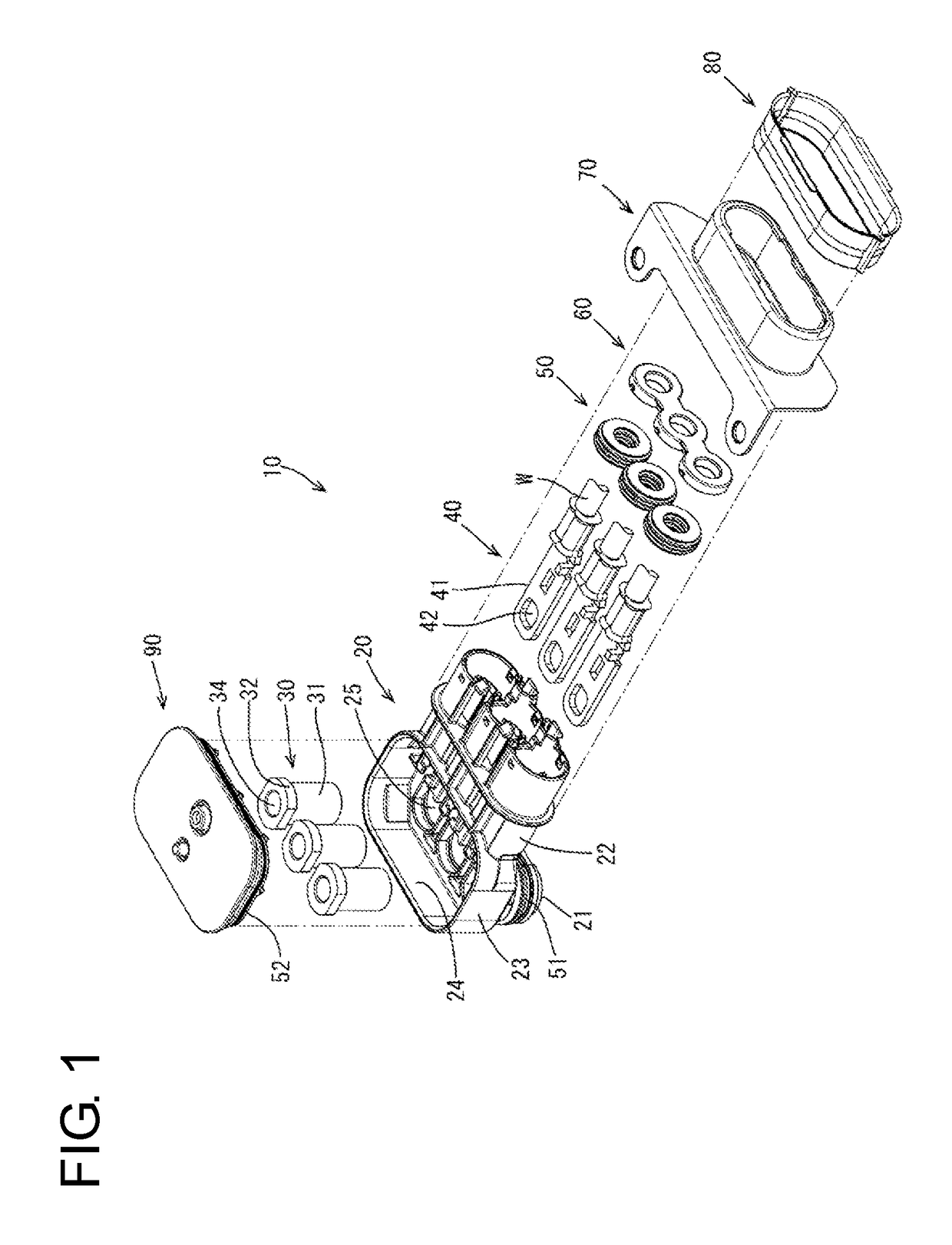
[0031]An embodiment is described with reference to FIGS. 1 to 14. A connector 10 of this embodiment is a shield connector for high current to be mounted on a casing 1 of a device such as an inverter and includes, as shown in FIG. 1, a housing 20, a plurality of hollow cylindrical intermediate terminals (hereinafter, abbreviated as “intermediate terminals”) 30, a plurality of terminals 40, a plurality of rubber plugs 50, a back retainer 60, a shield shell 70, a crimp ring 80, a cover 90 and the like. Alternatively, as shown in FIGS. 13 and 14, a mounting hole 2 is provided to be open upward in the casing 1 of the device, and a terminal block 3, mating terminals 4 and the like are disposed below the mounting hole 2.

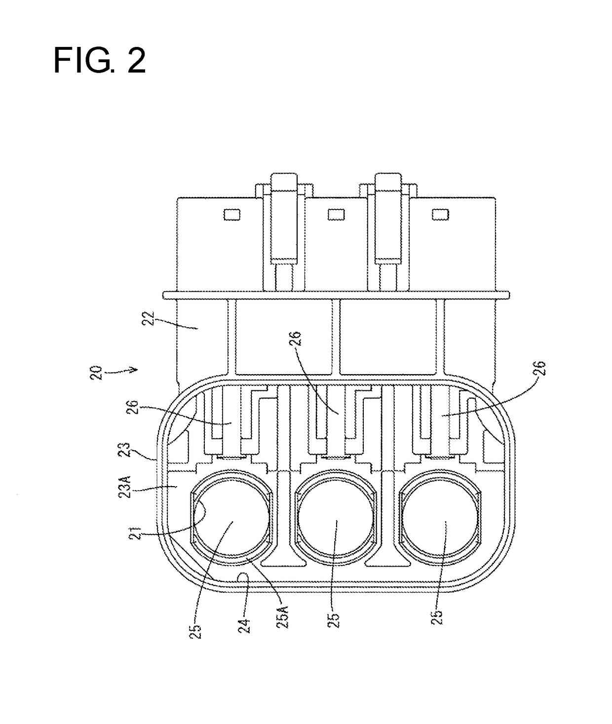
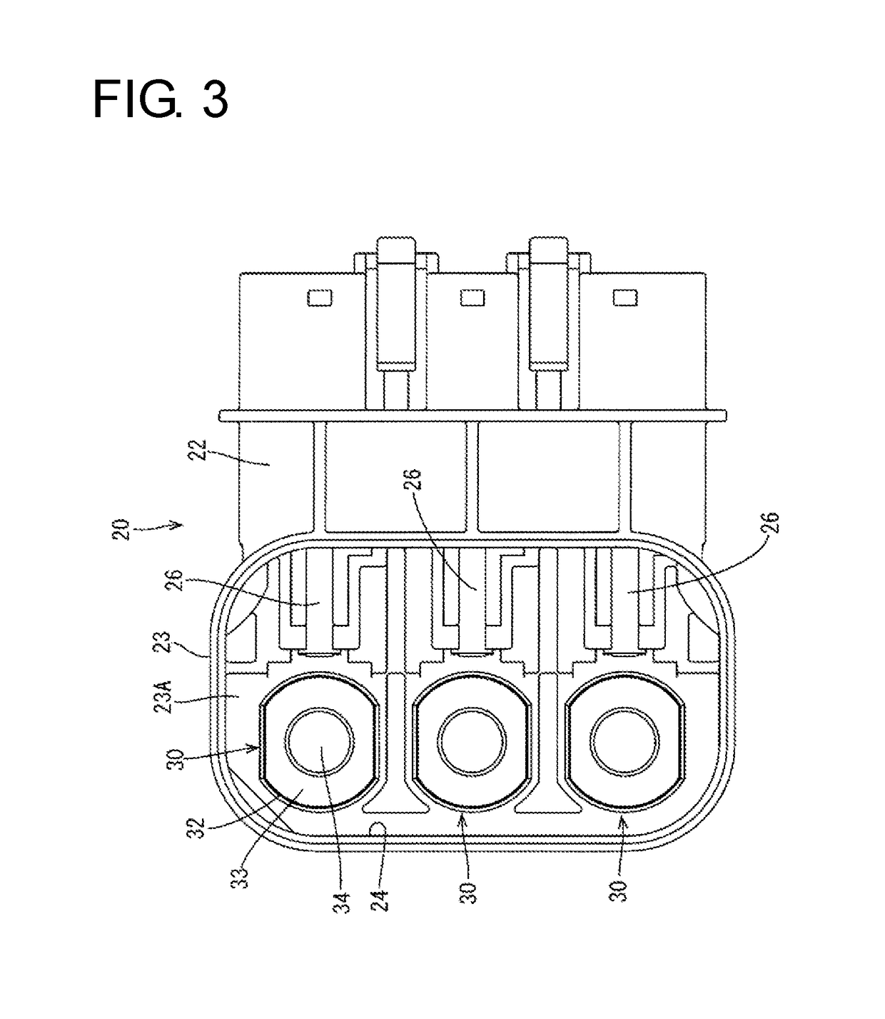
[0032]The housing 20 is made of synthetic resin and includes, as shown in FIG. 2, an intermediate terminal mounting portion 21 into which the intermediate terminals 30 are mounted, a terminal mounting portion 22 into which the terminals 40 are mounted and a cover mounting p...


PUM


Abstract

A connector 10 disclosed by this specification is a connector 10 to be mounted on a casing 1 of a device by being inserted into a mounting hole 2 provided in the casing 1 and includes a terminal 40 connected to a wire W, a housing 20 having the terminal 40 mounted therein, and an intermediate terminal 30 made of metal, mounted in the housing 20 and disposed between the terminal 40 and a mating terminal 4 in the casing 1. A fastened component (nut 5) disposed in the casing 1 and to be fastened to a fastening component (bolt B), the mating terminal 4, the intermediate terminal 30 and the terminal 40 are arranged side by side in a fastening direction, and the terminal 40 and the mating terminal 4 are connected via the intermediate terminal 30 by being collectively fastened by the fastening component and the fastened component.

Description

BACKGROUNDField of the Invention[0001]The invention relates to a connector.Description of the Related Art[0002]Japanese Unexamined Patent Publication No. 2015-18695 is an example of a known shield connector that is to be inserted into a mounting hole provided in a casing of a device. The shield connector includes a housing made of synthetic resin, a base-end side terminal to be connected to an end of a wire and a tip side terminal to be connected to the base-end side terminal. The tip side terminal includes a coupling plate to be connected to the base-end side terminal and a connecting piece to be connected to a mating terminal mounted in a device-side connector. The base-end side terminal and the coupling plate are connected by bolting, and a work opening for this bolting is open in the upper surface of the housing. After bolting, water is shut off from the interior of the housing by mounting a service cover on the work opening.[0003]In the above shield connector, since a connected...

Claims


Application Information

Patent Timeline
Patent Type & Authority Patents(United States)
IPC IPC(8): H01R4/30H01R43/20H01R13/6598H01R13/639H01R13/52H01R13/6581H01R13/516H01R12/71
CPCH01R4/30H01R13/516H01R13/52H01R13/6581H01R13/6598H01R43/20H01R13/6397H01R12/716H01R2105/00H01R4/308H01R4/34H01R9/223H01R11/12
Inventor OKAMOTO, MASAKIKOBAYASHI, MASAAKIOKAYASU, YASUSHIKITAGAWA, MASARU
Owner SUMITOMO WIRING SYST LTD
Why Eureka
Try Eureka