
Display device for vehicle

a technology for display devices and vehicles, applied in static indicating devices, dashboard fitting arrangements, instruments, etc., can solve problems such as difficulty in operation of touch panels, insufficient ease of visual recognition, and inability to operate, so as to improve visual recognition. the effect of eas

Active Publication Date: 2018-09-04
SUBARU CORP
View PDF51 Cites 12 Cited by
  • Summary
  • Abstract
  • Description
  • Claims
  • Application Information

AI Technical Summary

Benefits of technology

This configuration enhances operability and safety by allowing drivers to view and interact with the display without significant head movement, improving ease of use and reducing visual strain while driving.

Problems solved by technology

Accordingly, the driver or a passenger seated in the automobile has to reach forward to operate the operating unit, which is problematic in terms of operability.
Thus, the display device disclosed in JP-A No. 2012-022393 does have improved operability, but is insufficient with regard to ease of visual recognition, since the user has to continuously move the line of sight back and forth.
However, operation of the touch panel will be difficult, since of the proximity to the driver.
Further, the driver has to focus back and forth between faraway (outside the automobile) and up close (the touch panel), which is not necessarily suitable.
Now, such display devices generally tend to have a small-sized display screen, due to dimensional restrictions within the cabin.
Accordingly, displaying a great amount of information on such a display device results in the display size of the information being small, and hence difficult to view.

Method used


Image

  • Display device for vehicle
  • Display device for vehicle
  • Display device for vehicle

Examples


Embodiment Construction

First Implementation

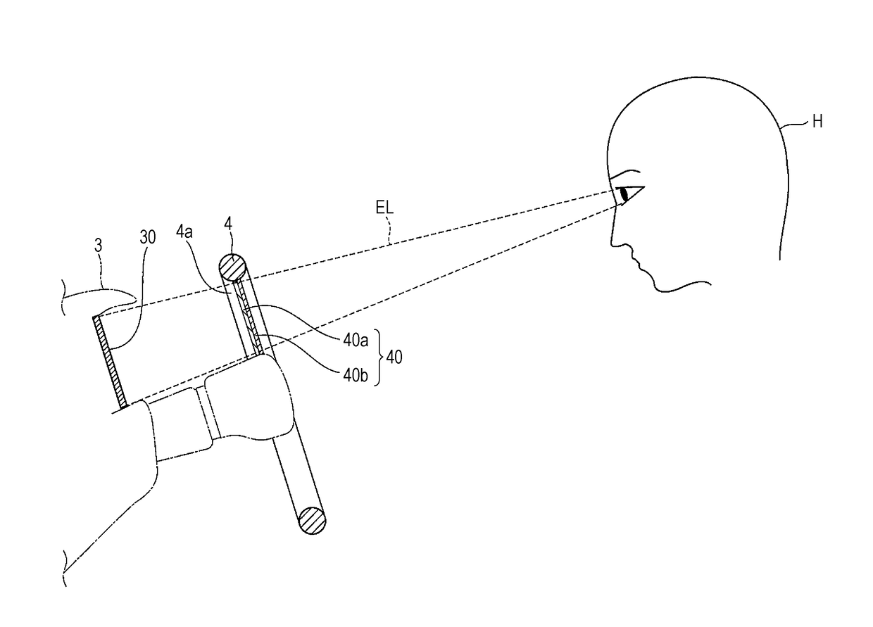
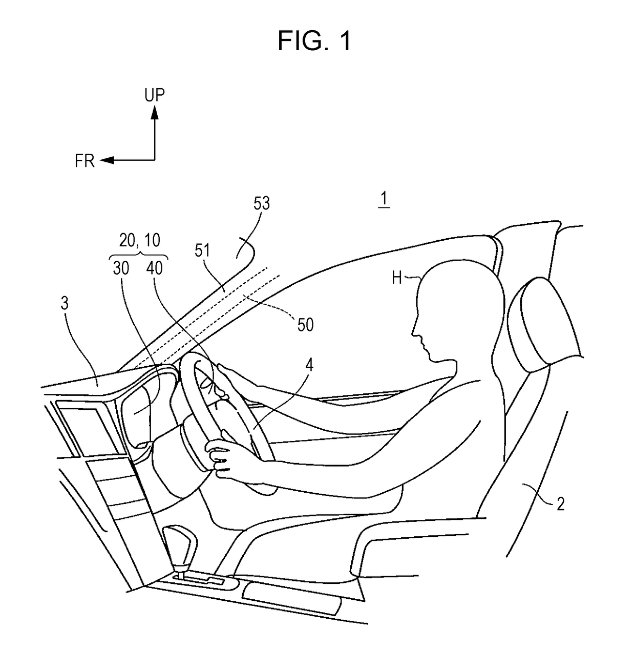
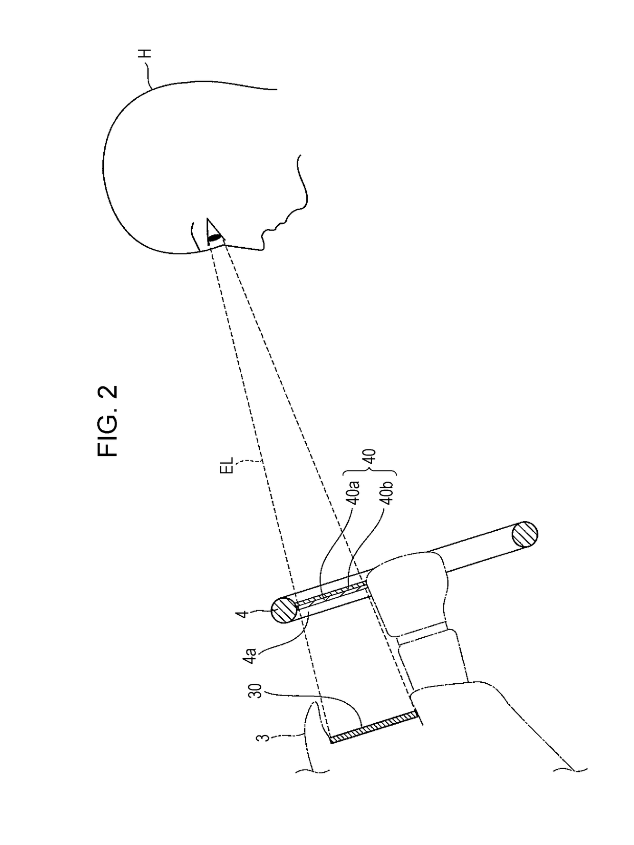
[0045]A first implementation of the present invention will be described based on the drawings. FIG. 1 is a perspective view illustrating inside of a cabin of a vehicle, according to a first implementation of the present invention, FIG. 2 is a side view illustrating the positional relation between driver, display panel, and input panel, FIG. 3 is a front view illustrating the display panel and input panel as viewed from the driver's seat, FIG. 4 is a block diagram for describing a control system provided to an automotive information display system, FIG. 5 is a diagram describing a “navigation menu screen”, as an example of an image displayed on the display panel, and FIG. 6 is a diagram describing a navigation screen, as an example of an image displayed on the display panel. Also, “FR” in FIG. 1 indicates the forward direction of the automobile, and “UP” indicates the upward direction. The terms “left” and “right” as used in the following description means left an...


PUM


Abstract

A display device for a vehicle includes an operating unit which a passenger can operate, and a display unit which displays various types of images based on an operation input at the operating unit. The operating unit and display unit are disposed separated from each other. The operating unit is situated between the eyes of a driver performing the operation input and the display unit, and overlays the display unit on the line-of-sight direction of the driver performing the operation input.

Description

CROSS-REFERENCE TO RELATED APPLICATIONS[0001]The present application claims priority from Japanese Patent Application Nos. 2013-073387, 2013-073388, 2013-073391, 2013-073392, 2013-073393, and 2013-073394, all filed on Mar. 29, 2013, the entire contents of which are hereby incorporated by reference.BACKGROUND[0002]1. Technical Field[0003]The present invention relates to a display device for a vehicle.[0004]2. Related Art[0005]Heretofore, there have been known display devices for a vehicle which can display various types of information, such as map information. Such a display device for a vehicle is disposed, for example, in an instrument panel of an automobile, at the middle thereof in the width direction (see Japanese Unexamined Patent Application Publication (JP-A) No. 2010-163114).[0006]Generally, such display devices for a vehicle have an integrally-formed display and operating unit. The display serves as a display unit, and the operating unit is arranged so as to enable input of...

Claims


Application Information

Patent Timeline
Patent Type & Authority Patents(United States)
IPC IPC(8): G09G5/00B60K37/06B60K35/00G06F3/14B60K35/10
CPCG06F3/1423B60K35/00B60K37/06B60K2350/2056B60K2350/1024B60K35/10B60K35/22B60K2360/143B60K2360/347
Inventor WAKAMOTO, NAOKINIWA, MAKOTOKONNO, DAIGO
Owner SUBARU CORP
Learn More