Linear post-regulator

a post-regulator and linear technology, applied in the direction of electroluminescent light sources, electric lighting sources, semiconductor lamp usage, etc., can solve the problems of high led ripple current, inability to completely correct, and dynamic resistance also tends to decrease in time, so as to achieve a favorable increase in light output

Active Publication Date: 2018-09-04
SIGNIFY HLDG BV
View PDF14 Cites 0 Cited by
  • Summary
  • Abstract
  • Description
  • Claims
  • Application Information

AI Technical Summary

Benefits of technology

[0010]The performance parameter which can be controlled by the post-regulator according to the invention can be the post-regulator loss or the flicker of the light output of the LED arrangement. The linear post-regulator according to the invention can advantageously reduce the losses of the post-regulation to a minimum, while at the same time allowing an adjustable compromise between capacitor size and flicker on the light output. For example, the linear post-regulator according to the invention can achieve essentially constant post-regulation loss or essentially constant flicker over the lifetime of the LED lighting arrangement. An advantage of the linear post-regulator according to the invention is that a minimum loss operation and / or a minimum current ripple operation is made possible while permitting the use of a smaller storage capacitor. The linear post regulator according to the invention can be realized using favourably inexpensive analogue components. The physical size of the linear post-regulator according to the invention can also be favourably small, so that it can be used in a variety of applications in which a lighting fixture housing has only a limited available space for additional circuitry, for example when the post-regulator according to the invention is used to retro-fit an existing product series. The terminal of the LED lighting load can be its cathode terminal (e.g. the cathode of the last LED in a string) or its anode terminal (e.g. the anode of the first LED in a string). The post-regulator according to the invention is preferably connected between the cathode of the LED lighting load and a node or input terminal of the power converter. For example, the last LED of an LED string can be connected to a circuit node of the post-regulator, and the power control output of the post-regulator can be connected to an appropriate node of the power converter.
[0013]An advantage of the LED lighting arrangement is that it can implement a cheap and compact LED driver. The linear post-regulator can be configured to ensure either constant post-regulation loss or constant flicker over the lifetime of the lighting arrangement, independently of the dynamic resistance of the LED load connected to the driver.
[0015]An advantage of the method according to the invention is that available information regarding current and voltage can be used in a favourably straightforward manner to generate specific control signals that regulate the LED current as well as one or more further performance parameters in order to achieve a desired mode of control.
[0019]In an alternative preferred embodiment of the invention, the level of flicker on the light output of the LED lighting load is controlled on the basis of a feedback signal from a control loop of the control loop cascade. In such an embodiment, the performance parameter comprises a reference current ripple that represents a “desired current ripple” or “desired flicker”, and the control loop cascade is realized to provide a feedback signal or power correction signal to the power converter to cause it to adjust the current ripple on the LED current accordingly. In such an embodiment, the lighting arrangement is operated in a “constant flicker” mode. A decrease of ripple or flicker on the post-regulated LED current can also lead to a favourable increase in light output, and can thereby compensate for any increase in post-regulator losses.

Problems solved by technology

However, this can lead to a high LED ripple current.
The ripple current might be compensated to some extent by a storage capacitor connected in parallel to the LEDs, but cannot be corrected entirely due to the limited dynamic resistance of the LEDs.
Due to the increasingly efficient LED technology, that dynamic resistance also tends to decrease further in time.
The pronounced ripple current can also adversely affect the luminous efficiency of the LEDs.
Existing linear post-regulators can be relatively inexpensive, but are generally associated with an increase in losses.
To cope with the resulting heat, additional or larger heat sinks are required, adding to the overall cost of a lighting application.
Another disadvantage of the known types of linear post-regulator is that the level of flicker on the light output can increase, since the storage capacitor can degrade down to 50% of its initial value during the lifetime of such a lighting arrangement.
It is difficult and / or costly to reduce post-regulator losses.
Some ways of addressing the problem are to improve thermal management by using a larger heatsink, as already mentioned, however this may unfavourably increase the overall size of the product and adds to the overall costs.
Alternatively, a switched-mode converter may be used as the second power stage, which can achieve an almost negligible flicker but which is significantly more expensive and bulky and also adds losses.
In another approach, a larger storage capacitor is used to avoid the need for a post-regulator; however the physical size of a capacitor increases with its value, and the cost increases also.
When no corrective measures are taken, the lamp may eventually exhibit noticeable flicker.

Method used


Image

  • Linear post-regulator
  • Linear post-regulator
  • Linear post-regulator

Examples


Embodiment Construction

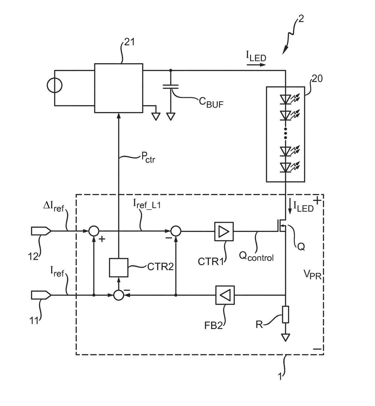
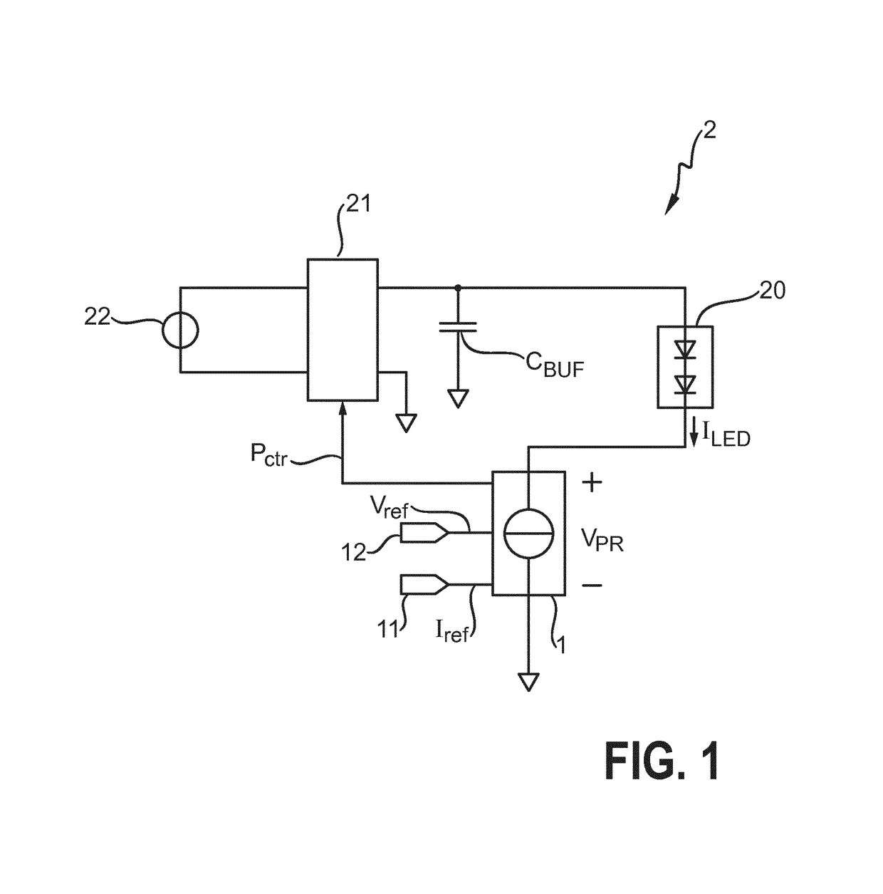
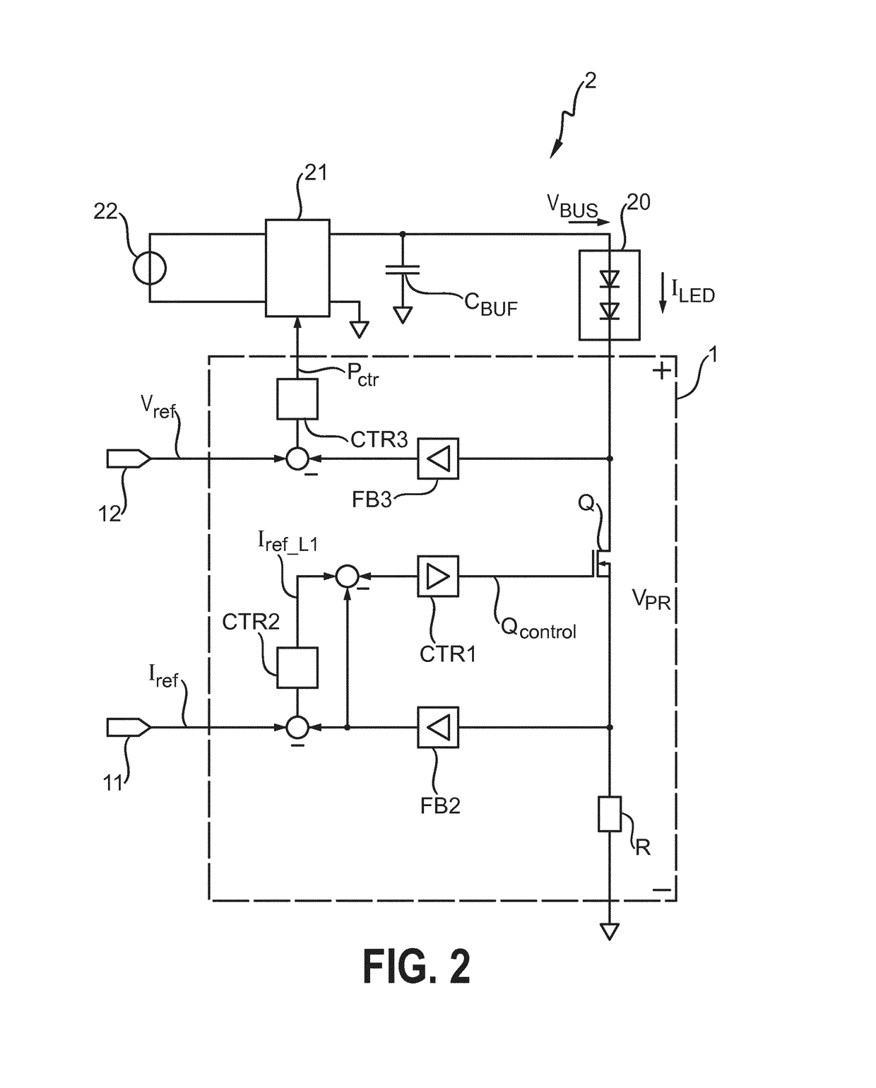
[0035]FIG. 1 shows a simplified schematic representation of an LED lighting arrangement 2 according to the invention. A power supply 22 delivers a rectified signal to a single-stage high power-factor (HPF) front-end switched-mode converter 21. A storage capacitor or buffer capacitor CBUF is connected across the outputs of the converter 21 and is arranged in parallel with a series arrangement comprising a lighting load 20 and a post-regulator 1 according to the invention. The post-regulator 1 according to the invention is realised for connection between a terminal cathode of the LED lighting load 20, and a terminal of the converter 21. The voltage VPR across the post-regulator 1 is indicated. The lighting load comprises an LED arrangement 20 as described above. The LED lighting arrangement 2 comprises the linear post-regulator 1 according to the invention, comprising a number of cascaded control loops to control the average LED current ILED and also to reduce the post-regulator losse...


PUM


Abstract

The invention describes a linear post-regulator (1) realized for use in an LED lighting arrangement (2), which linear post-regulator (1) comprises a control loop cascade (L1, L2, L3) realized for connection between a terminal of an LED lighting load (20) and a power converter (21) of the LED lighting arrangement (2); a transistor (Q) realized to regulate an LED current (ILED) through the LED lighting load (20); a first input (11) for connection to a reference current input (Iref); a second input (12) for connection to a performance parameter input (Vref, Δlref); and an output for connecting a power control output (Pctr) of the linear post-regulator (1) to the power converter (21); wherein the control loop cascade (L1, L2, L3) comprises at least two interconnected control loops (L1, L2, L3) to regulate the LED current (ILED) on the basis of the reference current input (Iref) and to regulate a further performance parameter of the LED lighting arrangement (2) on the basis of the performance parameter input (Vref, Δlref). The invention also describes an LED lighting arrangement (2), and a method of post-regulating the current of an LED lighting load (20) of an LED lighting arrangement (2).

Description

CROSS-REFERENCE TO PRIOR APPLICATIONS[0001]This application is the U.S. National Phase application under 35 U.S.C. § 371 of International Application No. PCT / EP2015 / 074793, filed on Oct. 27, 2015 which claims the benefit of European Patent Application No. 14191413.5, filed on Nov. 3, 2014. These applications are hereby incorporated by reference herein.FIELD OF THE INVENTION[0002]The invention describes a linear post-regulator, an LED lighting arrangement, and a method of post-regulating the current of an LED lighting load of an LED lighting arrangement.BACKGROUND OF THE INVENTION[0003]LED lighting is becoming more and more popular as manufacturing costs are reduced to offer affordable LED lamps for many fixture types. In one widespread type of LED lighting device for indoor or outdoor lighting, a rectifier is used to rectify a mains input, and an LED driver delivers the desired voltage and current levels to an LED arrangement comprising one or more strings of LEDs. For cost reasons,...

Claims


Application Information

Patent Timeline
Patent Type & Authority Patents(United States)
IPC IPC(8): H05B37/02H05B33/08H05B44/00
CPCH05B33/0812H05B37/0272H05B33/0848H05B45/395H05B45/375H05B47/19Y02B20/30H05B45/14
Inventor ELFERICH, REINHOLD
Owner SIGNIFY HLDG BV
Why Eureka
Try Eureka