Method and circuit arrangement for controlling a stepper motor

a stepper motor and circuit arrangement technology, applied in the direction of dynamo-electric converter control, dynamo-electric gear control, dynamo-electric brake control, etc., can solve the problem of low motor current difficulty, and achieve the effect of optimizing (and particularly calm) the operation of the stepper motor and small circuit complexity

Active Publication Date: 2018-09-11
MAXIM INTEGRATED PROD INC
View PDF8 Cites 2 Cited by
  • Summary
  • Abstract
  • Description
  • Claims
  • Application Information

AI Technical Summary

Benefits of technology

[0014]It is desirable to provide a method and a circuit assembly for operating a stepper motor, with which with a relatively small circuit complexity an optimized (and particularly calm) operation of a stepper motor, particularly with respect to a desired or target coil current course, can be obtained over a broad rotational speed range, i.e. between a standstill of the motor in which the motor is electrically fixed in a specific rotational position and a motor-related highest rotational speed.

Problems solved by technology

However, it has revealed that during this current-regulated operating mode particularly in case of a low rotational speed and standstill of the motor at an electrically fixed position (i.e. in a certain position of rotation) short-time current variations due to fluctuations of the regulation may occur in the audible frequency range which is undesired.
Such fluctuations of the regulation result from measuring or sampling noises, couplings within the motor and from interferences from other circuits or from the supply voltage.
Furthermore, it can be difficult at low motor currents in connection with the resulting only very short duration of the ON- and (if any) FD-phases and due to transient effects and blank times, to reliably measure during these short times the actually flowing coil current and to compare it with the instantaneous target coil current value.

Method used


Image

  • Method and circuit arrangement for controlling a stepper motor
  • Method and circuit arrangement for controlling a stepper motor
  • Method and circuit arrangement for controlling a stepper motor

Examples


Embodiment Construction

[0025]First, the implementation of the above three chopper phases during the current-regulated operating mode will be explained.

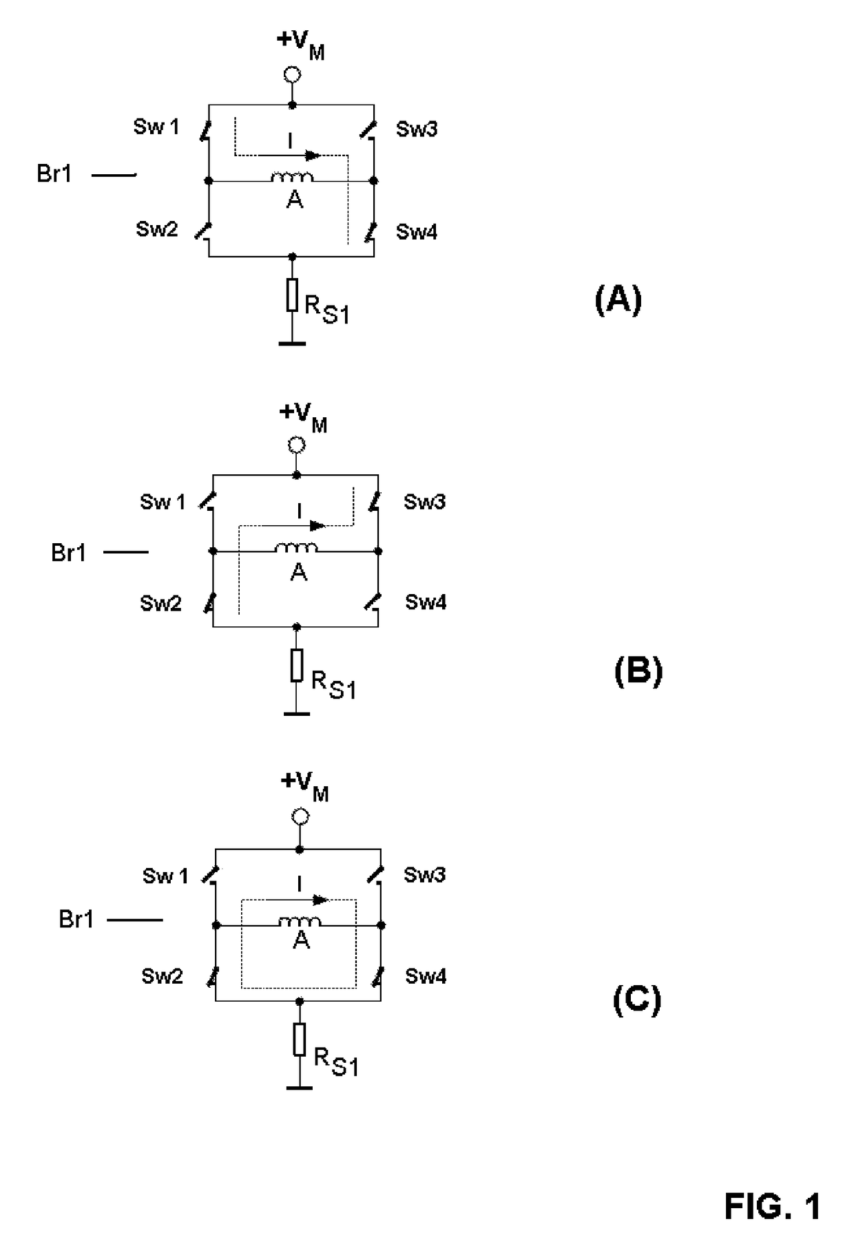
[0026]The three chopper phases are schematically shown in FIG. 1(A), FIG. 1(B) and FIG. 1(C), respectively. Each of these three figures shows a bridge circuit Br1 comprising a first to fourth switch Sw1, Sw2, Sw3, Sw4, wherein a first and a second switch Sw1, Sw2 as well as a third and a fourth switch Sw3, Sw4 are switched in series, and the two series connections are connected in parallel with each other. The motor coil A is connected with the center points of the bridge branches. The foot of the bridge circuit is connected via a measuring resistor RS1 to ground for measuring the actual current flowing in the motor coil, while the head of the bridge circuit is attached to a motor supply voltage VM. The switches Sw1, Sw2, Sw3, Sw4 are operated by means of a driver circuit to which the chopper switch signals are supplied for activating the chopper phases.

[00...


PUM


Abstract

A method and a circuit arrangement is described by means of which a stepper motor can be operated by an adaptive control over a large rotational speed range, including a standstill, in which the motor is electrically fixed in a specific rotational position, and with high precision and running smoothness corresponding to a specified motor current course. This is achieved essentially by the fact that the motor is operated in a low rotational speed range including a standstill with a voltage-controlled or voltage-regulated first operating mode and in a higher or high rotational speed range with a current-controlled second operating mode.

Description

BACKGROUND AND SUMMARY[0001]The invention relates to a method and a circuit arrangement by means of which a stepper motor can be operated by an adaptive control across a broad rotational speed range including a standstill in which the motor is electrically fixed in a specific rotational position, and with high precision corresponding to a predefined motor current course.[0002]It is generally known that in stepper motors a magnetic rotor is turned stepwise by each a small angle by means of a controlled rotating electromagnetic field which is generated with static motor coils.[0003]Frequently, it is desired to rotate the motor with as far as possible small step angles, in order to achieve an as high as possible resolution and exactness of the positioning and a uniform course of the motor torque. For these reasons, instead of the known full-step and half-step operation, the so called micro-step operation is preferred in which the currents flowing through the motor coils are not only sw...

Claims


Application Information

Patent Timeline
Patent Type & Authority Patents(United States)
IPC IPC(8): H02P21/04H02P23/00H02P8/18H02P8/12H02P8/22H02P8/04H02P8/34
CPCH02P8/18H02P8/04H02P23/0004H02P8/22H02P8/34H02P8/12H02P21/0017H02P8/14H02P8/30
Inventor DWERSTEG, BERNHARD
Owner MAXIM INTEGRATED PROD INC
Why Eureka
Try Eureka