Determination of relative positions

a technology of relative positions and camera modules, applied in the field of relative positions determination of equipment and fixtures, can solve the problems of no longer working properly, no continuous information provided by the camera module, and no workcell function

Active Publication Date: 2018-09-18
K2R2
View PDF29 Cites 5 Cited by
  • Summary
  • Abstract
  • Description
  • Claims
  • Application Information

AI Technical Summary

Benefits of technology

[0009]It is further desirable to provide the ability to locate items using passive camera systems and avoid the need for illuminators, scanning lasers, or devices that emit structured light. This improves the simplicity of system, avoid the cost of additional components, and eliminates risks associated with the use of lasers or other emitters around people.

Problems solved by technology

In either case, the robot arm and the fixture must remain in their calibrated positions or the workcell will no longer function properly.
In particular, the camera module does not provide continuous information on the position of any object or module.

Method used


Image

  • Determination of relative positions
  • Determination of relative positions
  • Determination of relative positions

Examples


Embodiment Construction

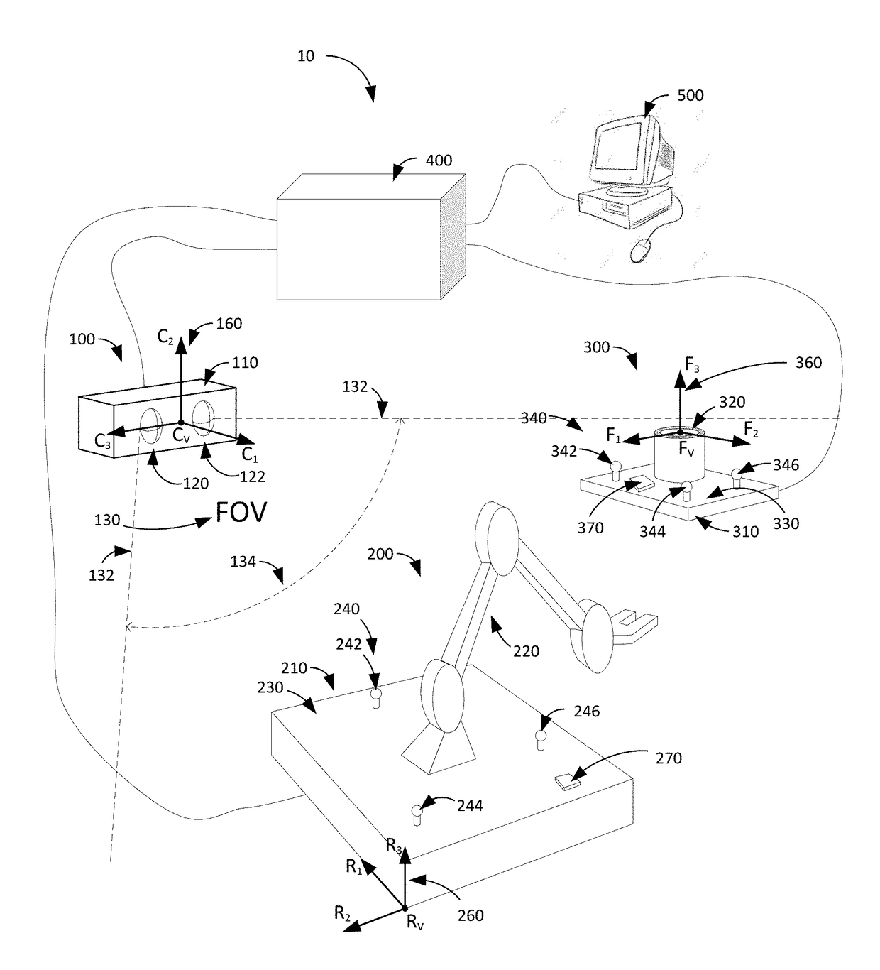
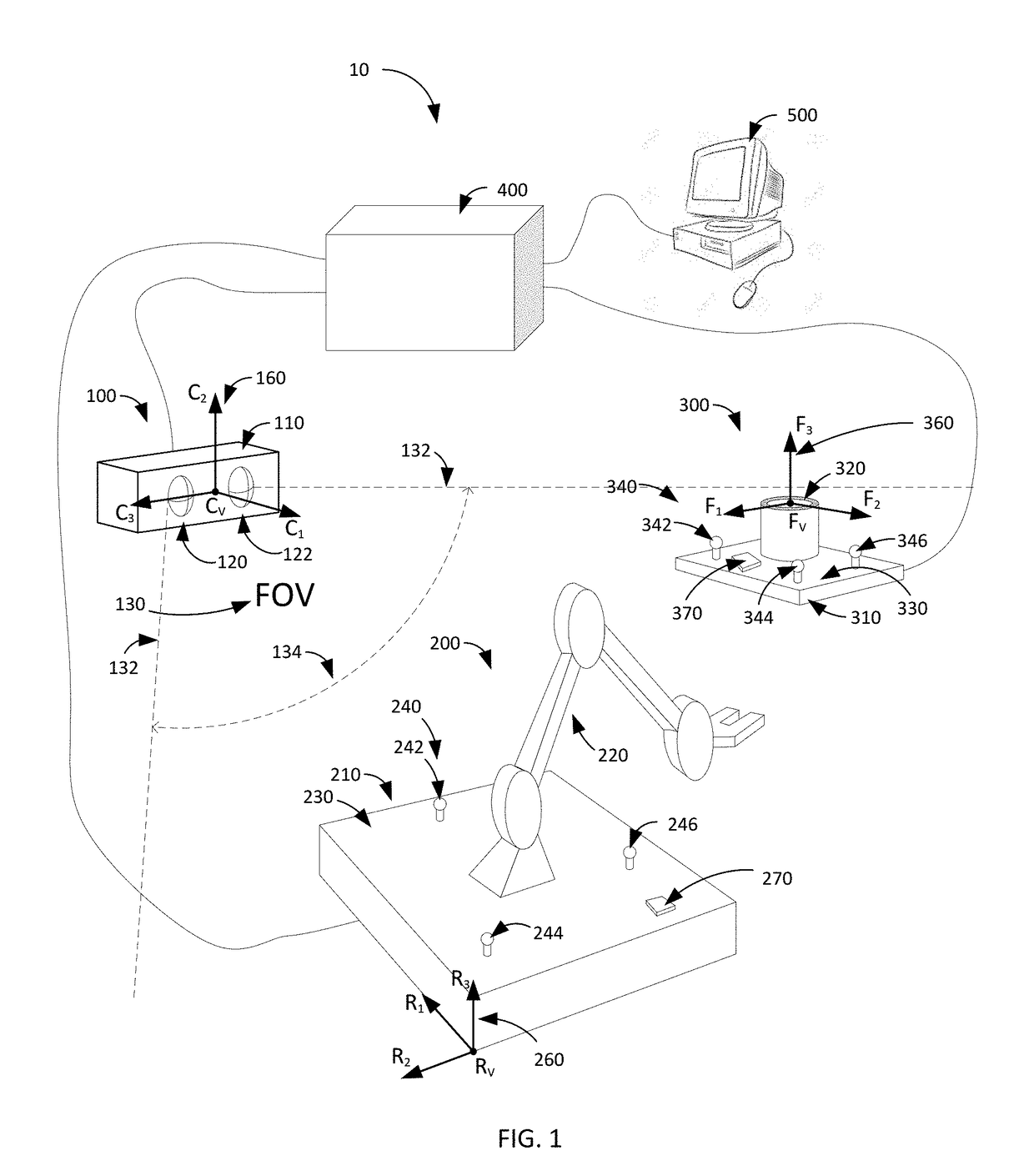
[0020]The following description discloses embodiments of a system and method of identifying the location and orientation of a robot arm, tools, fixtures, and other devices in a work cell or other defined volume of space.

[0021]The detailed description set forth below is intended as a description of various configurations of the subject technology and is not intended to represent the only configurations in which the subject technology may be practiced. The appended drawings are incorporated herein and constitute a part of the detailed description. The detailed description includes specific details for the purpose of providing a thorough understanding of the subject technology. However, it will be apparent to those skilled in the art that the subject technology may be practiced without these specific details. In some instances, well-known structures and components are shown in block diagram form in order to avoid obscuring the concepts of the subject technology. Like components are lab...


PUM


Abstract

A workcell has a camera module with two optical systems and a memory containing information about the arrangement of the optical systems, a robot module with a first coordinate system, a first set of fiducials, and a memory containing information about the 3D positions of the first set of fiducials defined within the first coordinate system, and a fixture with a second coordinate system, a second set of fiducials, and a memory containing information about the 3D positions of the second set of fiducials defined within the second coordinate system. A processor is communicatively coupled to the camera module, the robot module, and the fixture. The processor is configured to receive information about positions of each of the fiducials as observed by the two optical systems, retrieve from the various memories information about the arrangement of the first and second optical systems, the 3D positions of the first set of fiducials, and the 3D positions of the second set of fiducials, and determine the position and orientation of the fixture in the coordinate system of the robot module.

Description

CROSS-REFERENCE TO RELATED APPLICATIONS[0001]This application claims the benefit of U.S. Provisional Application Ser. No. 62 / 374,277, filed Aug. 12, 2016.STATEMENT REGARDING FEDERALLY SPONSORED RESEARCH OR DEVELOPMENT[0002]Not Applicable.BACKGROUNDField[0003]The present invention generally relates to determination of relative positions of equipment and fixtures in a workcell.Description of the Related Art[0004]Robotic workcells commonly use a robot arm to move items between locations, for example between a transport tray and a processing fixture. In current systems, the locations from which the item is picked up and where the item is to be placed must be known precisely by the controller of the robot arm as the robot moves blindly between positions. Set-up of a workcell therefore requires either precision placement of the fixture relative to the robot arm in pre-determined positions or calibration of the system after the robot arm and fixture are in place. In either case, the robot ...

Claims


Application Information

Patent Timeline
Patent Type & Authority Patents(United States)
IPC IPC(8): G06T7/70H04N5/225H04N5/247
CPCG06T7/70H04N5/247H04N5/2257Y10S901/47G06T2207/10012G06T2207/30164G06T2207/30204G06T7/73H04N13/239H04N23/57H04N23/90
Inventor KAY, ROBERT LROSS, GRAHAM
Owner K2R2
Why Eureka
Try Eureka