
Snap fastener

a technology of snap fasteners and snaps, applied in the field of snap fasteners, can solve the problems of limiting the selection of materials, and achieve the effects of reducing costs, speeding up delivery, and avoiding delay

Active Publication Date: 2018-09-25
DURAFLEX HONG KONG
View PDF9 Cites 2 Cited by
  • Summary
  • Abstract
  • Description
  • Claims
  • Application Information

AI Technical Summary

Benefits of technology

[0015]When implementing the snap fastener of the present application, the following advantageous effects can be achieved:
[0016](1) The face fastener of the present application can be separated into the face shell and the locating pin, which are snapped with each other, so that the locating pin can be manufactured into a standard part for batch production and storage, thereby speeding up delivery and avoiding delay because of a large workload.
[0017](2) As the face fastener of the present application can be separated into the face shell and the locating pin, the design of face shell can be variegated as required and be not limited by the material and the color of the locating pin.
[0018](3) The locating pin of the present application is made of plastic material, has portability and lower costs; moreover, need not adopt an electroplating step required by metal material, which is more beneficial to the recycling of resources and environmental protection.
[0019](4) The design of the anti-rotation protrusions can prevent the locating pin from rotating relative to the face shell effectively; moreover, the cross sections of the anti-rotation protrusions of the present application along a tangential direction of the base are designed to be an isosceles triangle, which can improve force balance of anti-rotation protrusions and enhance its strength to ensure it not easy to be broken.
[0020](5) The ridge portions of the anti-rotation protrusions extend along a radial direction of the base, and top angles of the anti-rotation protrusions are an obtuse angle, so that two side portions of the anti-rotation protrusion can be connected to the end face of the base smoothly; and when processed and assembled, the reliable occlusion between the fixing flange and anti-rotation protrusions can be completed easily, the gap and the looseness are not formed easily, which can avoid the fixing flange from over-bending and being broken.

Problems solved by technology

In the structure of the existing snap fastener, a face fastener configured for connecting with the pin and the box adopts an integrated structure mostly, and a structure and pattern of the face fastener has several versions usually according to the needs of design; the integrated structure demands that its face and leg should adopt the same material, which limits the selection of materials; even if a little change of the pattern or shape of the surface of the face fastener happens, the whole face fastener should be remade, so that the face fastener can't be manufactured into a standard part for batch production and storage; when different kinds of the snap fasteners are manufactured every time, the delay is caused because of a large workload.

Method used


Image

  • Snap fastener
  • Snap fastener
  • Snap fastener

Examples


first embodiment

1-10

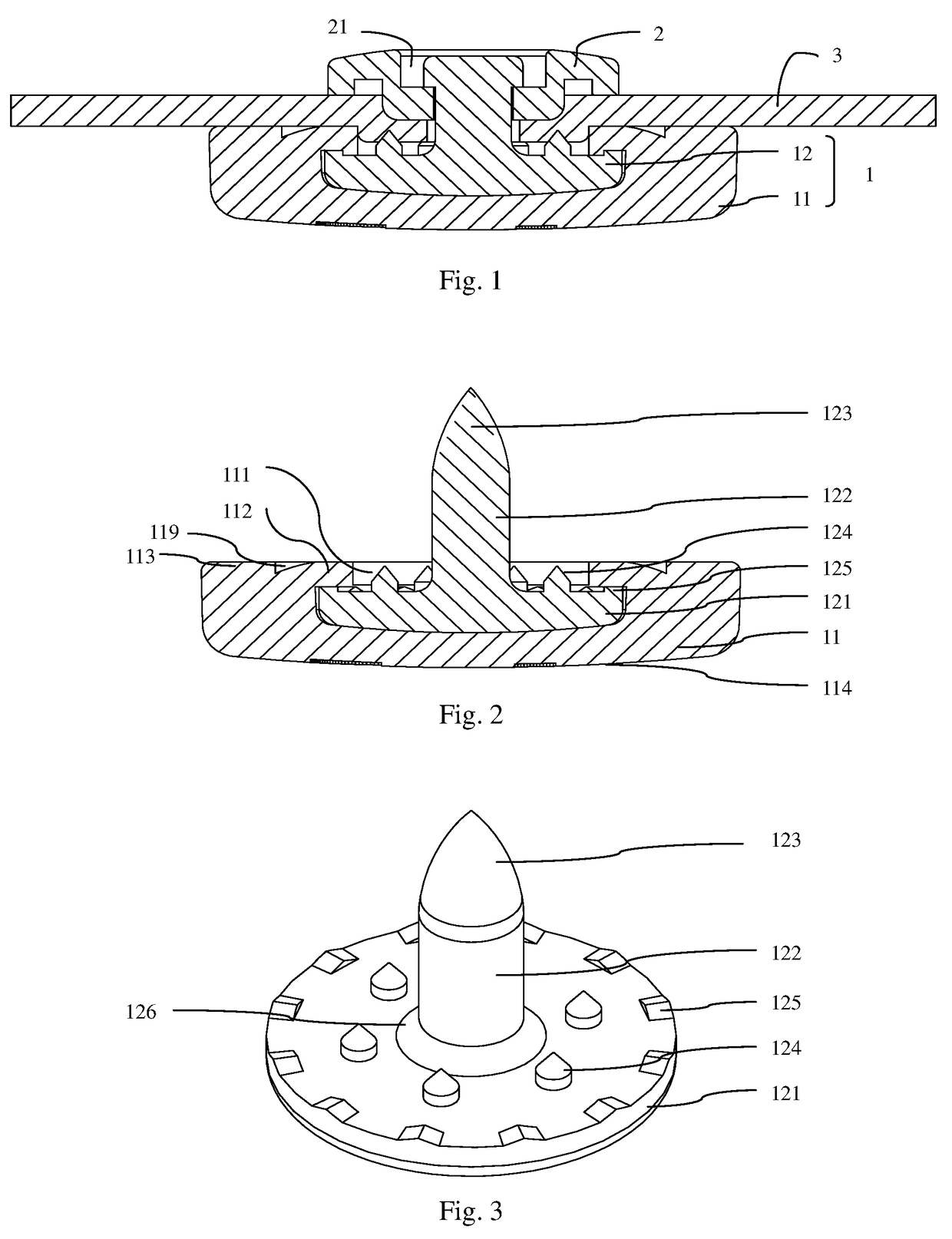
[0045]The FIG. 1 shows a snap fastener provided by the first preferred embodiment of the present application, and the snap fastener comprises a face fastener 1 and a locating fastener 2, which are snapped with each other. The locating fastener 2 can be a pin having a protruding rod structure as required, or can be a box having a recess structure, which is not specifically limited hereof.

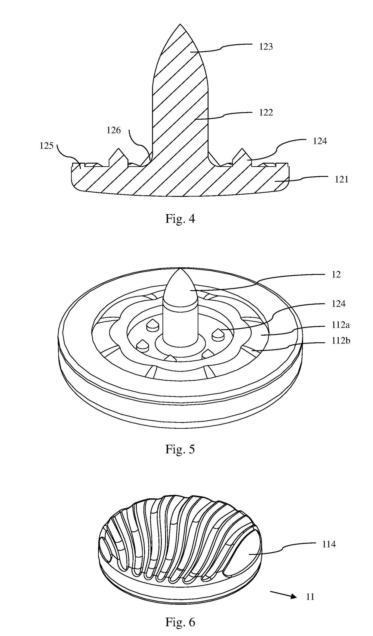
[0046]In the embodiment, the face fastener 1 comprises a face shell 11 and a locating pin 12, which can be separable from each other. One end of the locating pin 12 is connected to the face shell 11, and the other end of the locating pin 12 passes through the substrate 3 and is connected to the locating fastener 2, so that the two sides of the substrate 3 are clamped by the face fastener 1 and the locating fastener 2 respectively. The substrate 3 can be made of fabric, plastic, leather, artificial leather or non-woven fabric, etc., and can usually be used for manufacturing bag bodies, shoe bodies...

second embodiment

b>11 and 12

[0070]The face shell 11 of the present embodiment is made of plastic, and the difference between the present embodiment and the first embodiment lies at: the face shell 11 and the locating pin 12 in the present embodiment are assembled to form the face fastener 1 by way of heat-pressing as shown in FIGS. 11 and 12.

[0071]When assembled, the base 121 of the locating pin 12 is inserted down in the installation chamber 111 firstly, and abuts against the bottom of the installation chamber 111; and then, through heat-pressing, the fixing flange 112 is deformed thermally, and is bent towards the rod body 122 to cover the anti-rotation protrusions 125 completely; and the inner surfaces of the fixing flange 112 are arranged around the anti-rotation protrusions 125 to form concavo-convex occlusion, so that the disc-shaped fixing flange 112 abuts against the base 121 of the locating pin 12. The fixing flange 112 fits and abuts against the anti-rotation protrusions 125 to prevent the...

third embodiment

13-14

[0074]The difference between the present embodiment and the aforementioned embodiment is: the face shell 11 of the present embodiment is formed out of the locating pin 12 directly by way of injection molding.

[0075]When assembled, the manufactured locating pin 12 is arranged in an injection mold; by way of the injection molding, the face shell 11 covers the base 121 of the locating pin 12 directly; and the injection molded face shell 11 completely covers the anti-rotation protrusions 125 and is meshed therewith to prevent the locating pin 12 from moving or rotating in the face shell 11; and the anti-skidding structures 124 and the rod body 122, located at the center of the end face of the base 121 are exposed out of the installation chamber 111 to prevent the face fastener 1 from sliding relative to the substrate 3.

[0076]Because the face shell 11 is a concave-convex structure formed directly by way of injection molding and meshed with the locating pin 12, the fixing flange 112 n...


PUM


Abstract

Disclosed is a snap fastener, comprising a face fastener (1) and a locating fastener (2) which are snapped with each other, wherein the face fastener (1) comprises a face shell (11) provided with an installation chamber (111), and a locating pin (12) made of plastic and integrally formed; and the locating pin (12) comprises a base (121), a rod body (122) and anti-rotation protrusions (125). In the implementation of the snap fastener of the present invention, the face fastener (1) can be separated into the face shell (11) and the locating pin (12), and the locating pin (12) is manufactured into a standard part for batch production and storage, thereby adapting face shells (11) with continuously updated designs, shortening delivery time, and reducing costs.

Description

FIELD OF THE INVENTION[0001]The present application relates to a field of daily life, and more particularly relates to a snap fastener.BACKGROUND OF THE INVENTION[0002]A structure of the existing snap fastener comprises a pin and a box which are snapped with each other, wherein, a protruding rod vertically extending outwards and with concave edges is arranged on an end face of a base of the pin; a recess corresponding to the protruding rod is defined in an end face of the box; and protruding blocks are distributed around an opening of the recess. When used, the pin and the box are respectively mounted on sheet substrates to be connected and with through-holes; and in the presence of inherent elasticity of snap fastener materials, the protruding rod of the pin is pressed into the recess of the box, and protruding blocks are fixed in the concave edges, so that two sheet substrates to be connected can be connected together.[0003]In the structure of the existing snap fastener, a face fa...

Claims


Application Information

Patent Timeline
Patent Type & Authority Patents(United States)
IPC IPC(8): A44B1/34A44B17/00A44B1/14
CPCA44B17/0005A44B1/14A44B17/0082A44B17/0076Y10T24/3611A44B1/34A44B17/00
Inventor CHEN, TE CHIEN
Owner DURAFLEX HONG KONG
Learn More