Microfluidic-based electrospray source for analytical devices with a rotary fluid flow channel for sample preparation

a microfluidic and electrospray source technology, applied in the direction of fluid speed measurement, chemical vapor deposition coating, particle separator tubes, etc., can solve the problems of lif not being an ideal detection method, requiring the fluorescent analyte of interest, and the laser-induced fluorescence detection method is mostly limited, so as to reduce the production of waste, reduce the cost of manufacturing and operation, and reduce the consumption of resources

Inactive Publication Date: 2008-10-28
FLUIDIGM CORP
View PDF238 Cites 112 Cited by
  • Summary
  • Abstract
  • Description
  • Claims
  • Application Information

AI Technical Summary

Benefits of technology

[0025]Preferably, the microfluidic device of the present invention further comprises a second elastic layer which is positioned on top of the first elastic layer. In one embodiment of the present invention, the second elastic layer comprises a pressure channel which can act as pumps and valves for controlling the flow of fluid within the fluid flow channel in the first elastic layer. Thus, microfluidic devices of the present invention have significant advantages in both the sample preparation and sample delivery (in scales of nL / min). For example, in sample preparation, the combination of miniaturized valves and pumps on top of the first elastic layer allows one to conduct complex sample preparation processes, thereby circumventing shortcomings (some of which are described above) of electroosmotically driven microfluidic devices.
[0026]Other benefits of microfluidic devices of the present invention include reduced manufacturing and operating costs, reduced resource consumption, reduced waste production, and increased throughput (e.g., both by speeding up sequential, individual runs and also by implementing parallel processing). Further advantages of microfluidic devices of the present invention include adaptation of traditional LC packing materials that enable separations to be permitted on the device. The revolutionized sample processing and biochemical analysis provided by the present invention create “flow” or on-line systems, which can be adapted to high throughput methods.

Problems solved by technology

However, the method of detection has been mostly limited to laser-induced fluorescence (LIF) because of its simplicity and sensitivity.
One of the limitations of LIF is that it requires the analyte of interest to be fluorescent.
Since most compounds are not natural fluorophores, LIF is not an ideal detection method.
However, such proteomic studies, in which proteins are identified by analysis of enzymatically produced peptide fragments, are expensive and labor-intensive.
Technical difficulties exist in both sample separation and sample delivery systems for using ESI-MS in analysis of proteins, primarily because the samples that can be isolated from traditional gel-based electrophoresis are in very limited amounts.
This makes them difficult to analyze in a traditional ESI-MS configuration.
However, Nano-ESI-MS is labor-intensive and slow (in current designs, sample loading and set-up of the electrospray capillary are both manual processes).
In addition, it cannot be readily adapted to on-line capillary separation methods such as liquid chromatography or capillary electrophoresis.
For these reasons, nanospray is most often used as a “static” or off-line method in which samples are analyzed one-at-a-time, representing a serious bottleneck in applications that requires high throughput.
Software that integrates the variety of analytical methods required to perform high throughput analysis using these systems is already available, thus design of a robust multi-use interface is the bottleneck in adapting nanospray to high throughput applications.
However, these methods utilize non-elastic microfluidic devices and require fabricating an electrospray nozzle directly on the microfluidic device or attaching a capillary electrospray emitter to the microfluidic device.
Unfortunately, fabrication of an electrospray nozzle directly on the microfluidic device increases the manufacturing complexity, the production time and the cost.
Methods for attaching a capillary electrospray emitter to current microfluidic devices also have severe limitations.
More significantly, it is difficult to attach an electrospray emitter to non-elastic microfluidic device without introducing a certain amount of void volume.
Furthermore, the electrospray emitter must be carefully attached to the microfluidic device making mass production using batch processes difficult.
These fluid flow methods further limit the utility of these microchips.
For example, use of electroosmotic flow is incompatibility with many buffer systems, may cause molecular dissociation, and molecules can be damaged or degraded due to exposure to electric fields.
Most importantly the ionic buffers required to drive electroosmotic flow interfere with electrospray ionization and limit its usefulness.
The use of electric fields is also incompatible applications that demand the use of non-aqueous solvents.

Method used


Image

  • Microfluidic-based electrospray source for analytical devices with a rotary fluid flow channel for sample preparation
  • Microfluidic-based electrospray source for analytical devices with a rotary fluid flow channel for sample preparation
  • Microfluidic-based electrospray source for analytical devices with a rotary fluid flow channel for sample preparation

Examples


Embodiment Construction

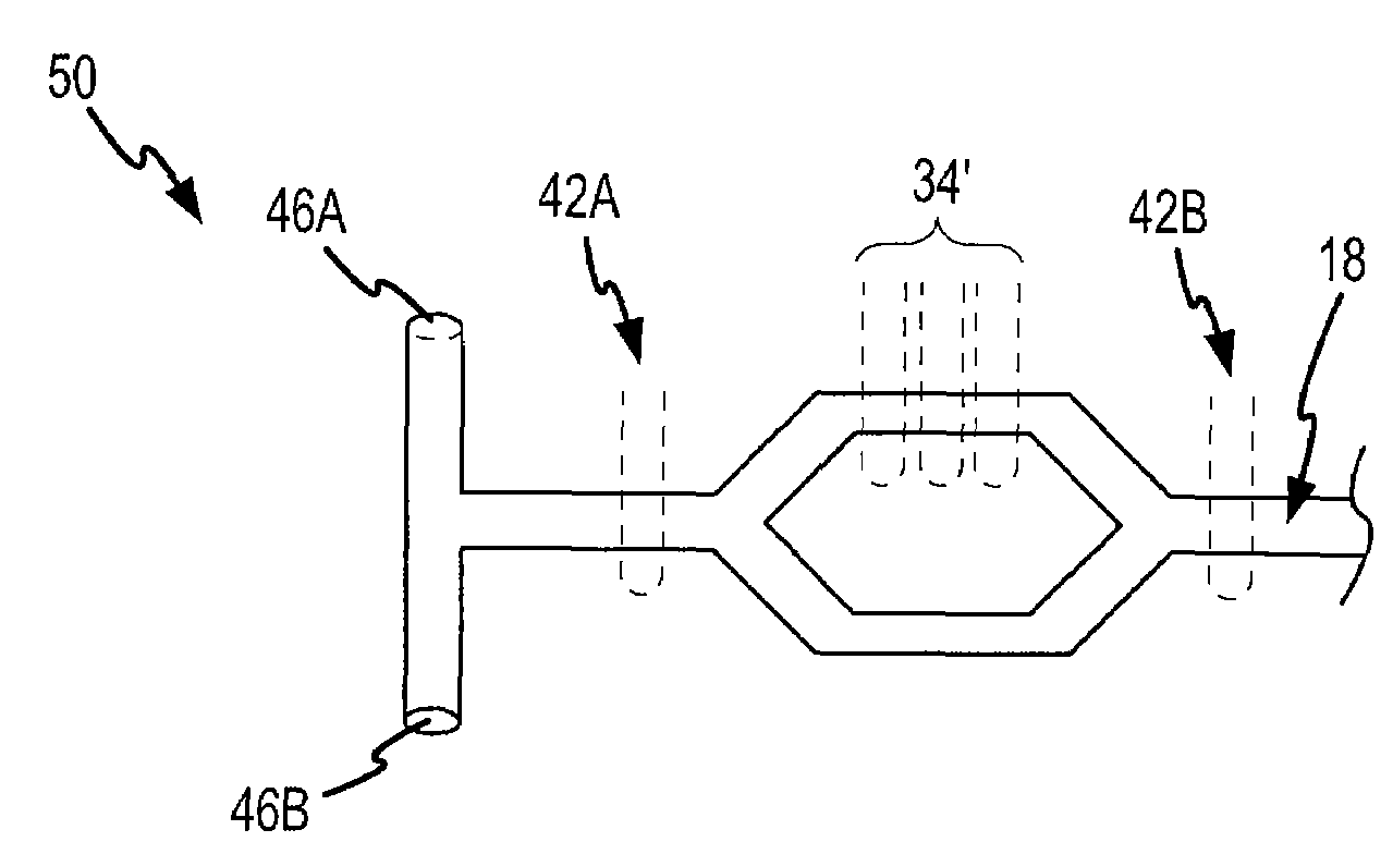
[0061]The present invention will be described with regard to the accompanying drawings which assist in illustrating various features of the invention. In this regard, the present invention generally relates to a microfluidic device comprising a means for providing a fluid sample from to an analytical device, an analytical apparatus comprising the same, and methods for using the same. The same numbers in different drawings represent identical elements. The drawings are provided for the purpose of illustrating the practice of the present invention and do not constitute limitations on the scope thereof.

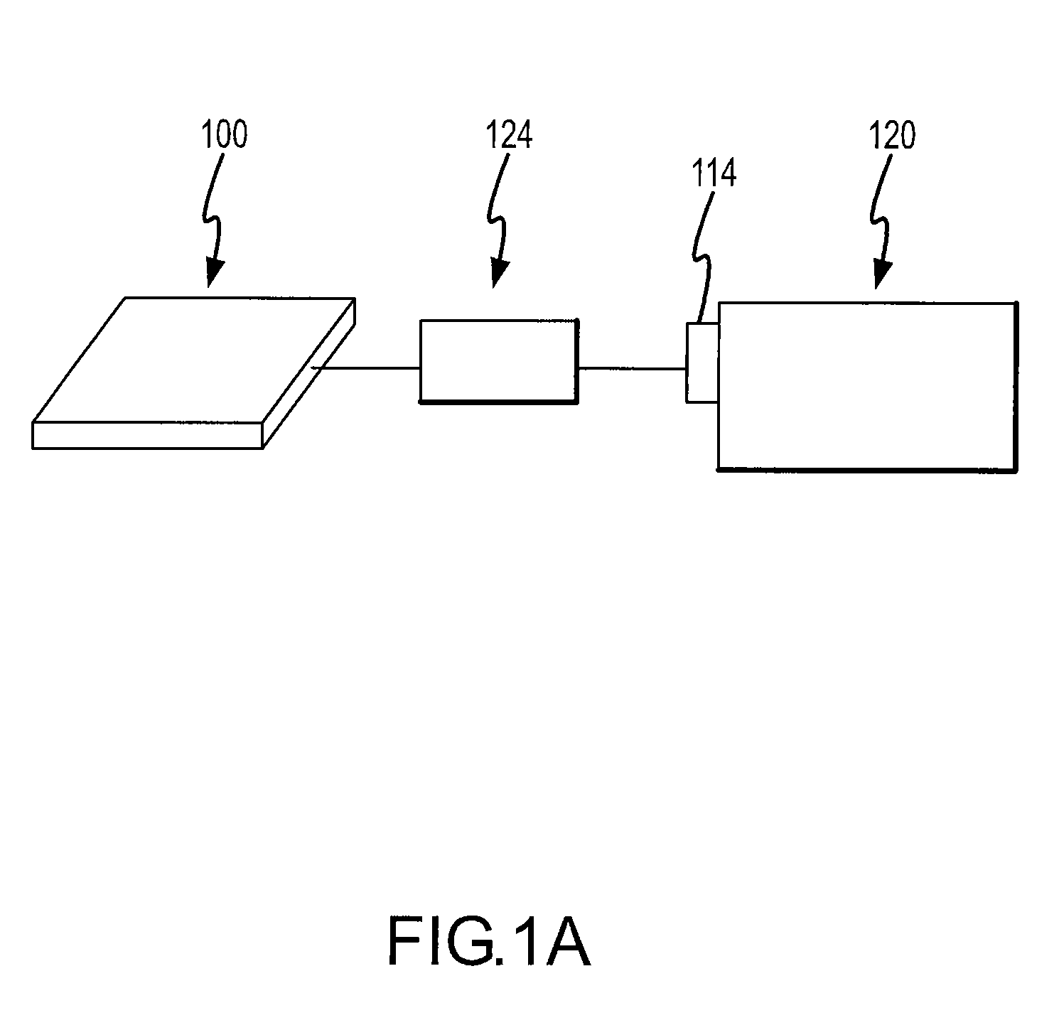
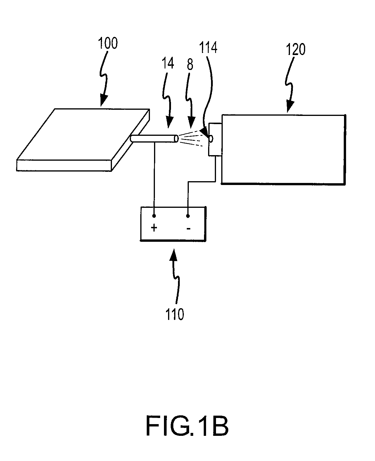
[0062]The analytical device 120 can be any device which is used for analyzing a chemical compound. Typically the analytical device 120 has a sample injection port 114 for introducing a sample to be analyzed. While the sample can be in a pure form (i.e., neat), microfluidic devices of the present invention are particularly useful for analyzing compounds which are in a solution.

[0063]Prefe...


PUM

PropertyMeasurementUnit
Young's modulusaaaaaaaaaa

Abstract

This invention provides microfluidic devices and methods for using the same. Microfluidic devices of the present invention comprises a first elastic layer, a fluid flow channel within the elastic layer; and a means for providing a fluid sample from the fluid flow channel to an analytical device. The present invention also provides an analytical apparatus comprising such a microfluidic device and an analytical device.

Description

FIELD OF THE INVENTION[0001]This invention relates to microfluidic devices and methods for using the same. In particular, microfluidic devices of the present invention comprise a fluid flow channel and a means for providing a fluid sample from the fluid flow channel to an analytical device.BACKGROUND OF THE INVENTION[0002]Recently, microfluidic devices capable of conducting chemical reactions and assays on a single microchip have been developed. However, the method of detection has been mostly limited to laser-induced fluorescence (LIF) because of its simplicity and sensitivity. One of the limitations of LIF is that it requires the analyte of interest to be fluorescent. Since most compounds are not natural fluorophores, LIF is not an ideal detection method. Thus, in order to use LIF detection method, a derivatization step is often required to make compounds of interest amenable to LIF detection.[0003]Mass spectrometry (MS) is currently being investigated as an alternative detection ...

Claims


Application Information

Patent Timeline
Patent Type & Authority Patents(United States)
IPC IPC(8): G01N1/10B01D59/44A61L15/38A61L15/40B01L3/00B01L3/02B81B1/00B81C1/00G01N30/72H01J49/04
CPCH01J49/0018H01J49/165B01L3/5027B01L3/0241Y10T436/25B01L3/502707B01L3/502715B01L3/50273B01L2200/027B01L2300/0816B01L2300/0887B01L2400/0481G01N30/7266Y10T436/25375Y10T436/25125Y10T436/2575Y10T436/24Y10T436/117497G01N1/10
Inventor MANGER, IAN DAVIDHAO, CUNSHENG CASEYUNGER, MARC ALEXANDER
Owner FLUIDIGM CORP
Why Eureka
Try Eureka