Fuel injector including tandem vanes for injecting alternate fuels in a gas turbine

a fuel injector and gas turbine technology, which is applied in the direction of continuous combustion chamber, combustion process, lighting and heating apparatus, etc., can solve the problems of different fuel properties, flashback in the turbine engine combustor, and relatively high flame speed

Inactive Publication Date: 2018-09-25
SIEMENS ENERGY INC
View PDF4 Cites 3 Cited by
  • Summary
  • Abstract
  • Description
  • Claims
  • Application Information

AI Technical Summary

Problems solved by technology

Use of fuels having different fuel properties can pose various challenges.
Another challenge is that fuels having a high hydrogen content can result in a relatively high flame speed compared to natural gas, and the resulting high flame speed can lead to flashback in the combustor of the turbine engine.

Method used


Image

  • Fuel injector including tandem vanes for injecting alternate fuels in a gas turbine
  • Fuel injector including tandem vanes for injecting alternate fuels in a gas turbine
  • Fuel injector including tandem vanes for injecting alternate fuels in a gas turbine

Examples


Embodiment Construction

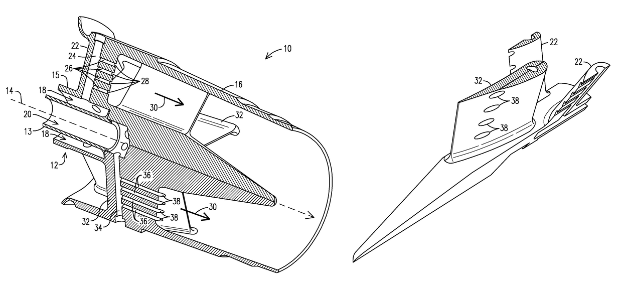
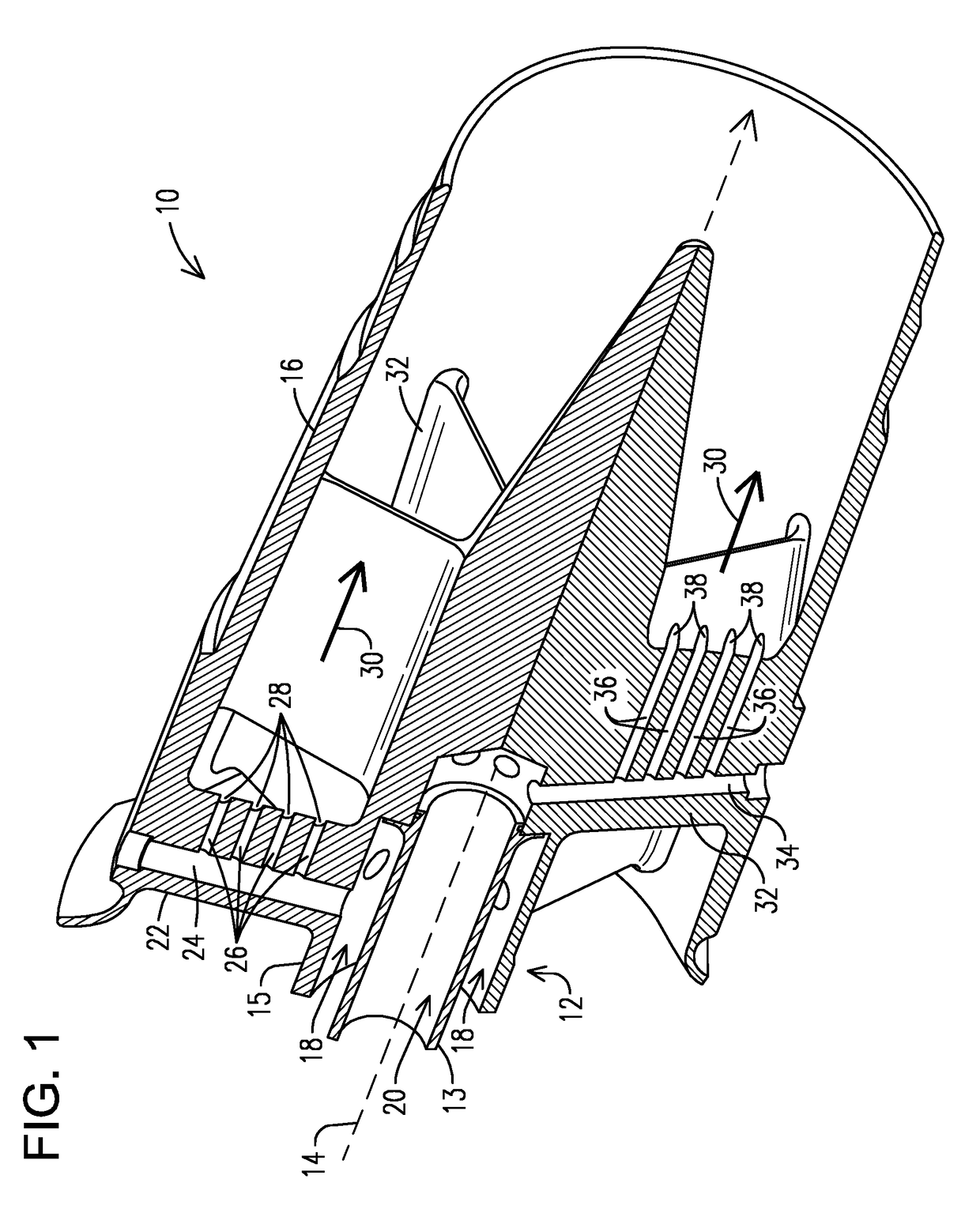
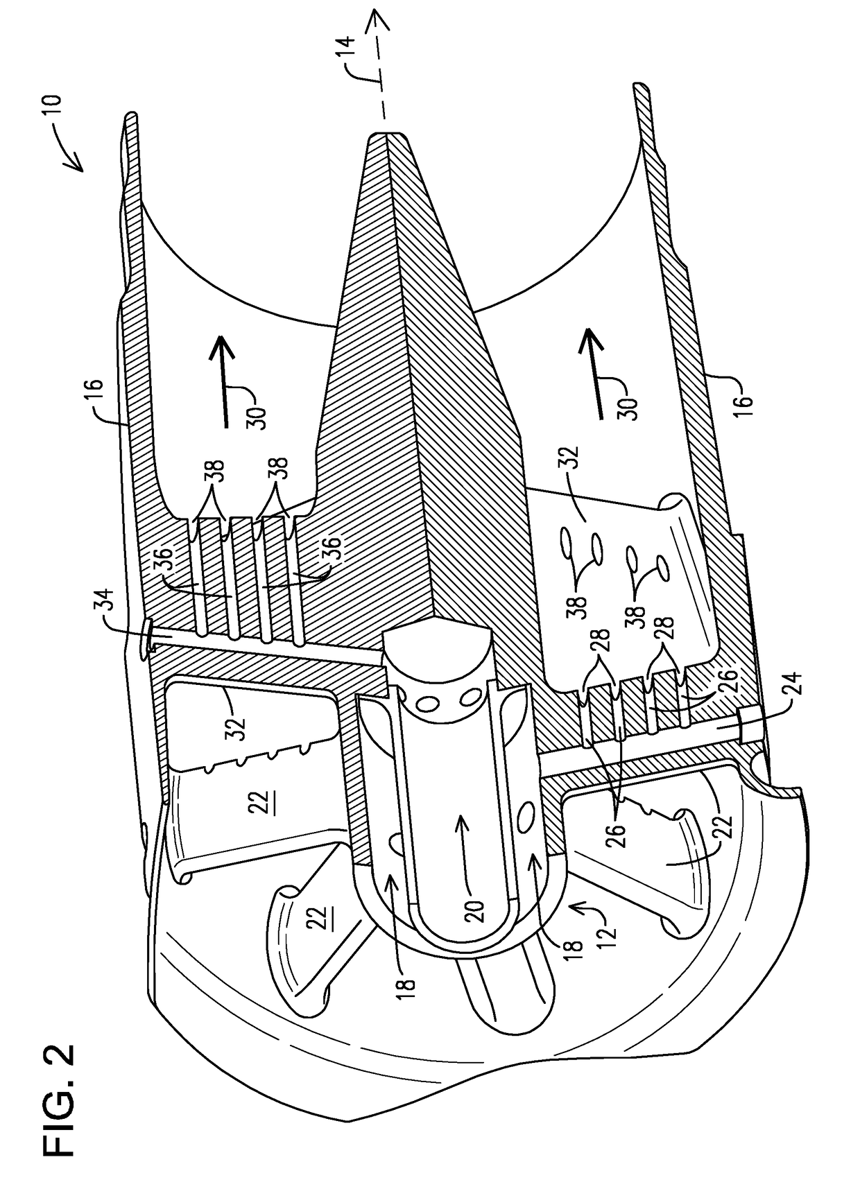
[0011]The inventors of the present invention have recognized certain issues that can arise in the context of certain prior art fuel injectors that may involve tandem vanes for injecting alternate fuels in a gas turbine. For example, some known fuel injector designs involve tandem vanes using a jet in cross-flow injection to obtain a well-mixed fuel / air stream into the combustor of the turbine engine. However, such designs may exhibit a tendency to flashback, particularly in the context of fuels with high hydrogen content. In view of such recognition, the present inventors propose a novel fuel injector arrangement where fuel is injected without jet in cross-flow injection, such as in the direction of the air flow intake in lieu of the traditional jet in cross-flow injection.

[0012]In the following detailed description, various specific details are set forth in order to provide a thorough understanding of such embodiments. However, those skilled in the art will understand that embodime...


PUM


Abstract

A fuel injector for injecting fuels having a different energy density in a gas turbine is provided. A first fuel supply channel (18) and a second fuel supply channel (20) may be coaxially arranged in a fuel delivery structure (12). A first set of vanes 22 includes a radial passage (24) in fluid communication with the first channel (18) to receive a first fuel. Passage (24) branches into passages (26) each having an aperture (28) to inject the first fuel without jet in cross-flow injection. A second set of vanes (32) includes a radial passage (34) in fluid communication with the second channel (20) to receive a second fuel. Passage (34) branches into passages (36) each having an aperture (38) arranged to inject the second fuel also without jet in cross-flow injection. This arrangement may be effective to reduce flashback that otherwise may be encountered in fuels having a relatively high flame speed.

Description

STATEMENT REGARDING FEDERALLY SPONSORED DEVELOPMENT[0001]Development for this invention was supported in part by Contract No.DE-FC26-05NT42644, awarded by the United States Department of Energy. Accordingly, the United States Government may have certain rights in this invention.BACKGROUND[0002]1. Field[0003]Disclosed embodiments are generally related to fuel injectors for a gas turbine, and, more particularly, to fuel injectors including tandem vanes for injecting alternate fuels, such as may comprise fuels having a different energy density.[0004]2. Description of the Related Art[0005]Economic considerations have pushed the development of gas turbines capable of using alternate fuels, such as may involve synthetic gases (e.g., syngas) in addition to using fuels, such as natural gas and liquid fuels, e.g., oil. These synthetic gases typically result from gasification processes of solid feedstock such as coal, pet coke or biomass. These processes may result in fuels having substantial...

Claims


Application Information

Patent Timeline
Patent Type & Authority Patents(United States)
IPC IPC(8): F23R3/28
CPCF23R3/286F23R3/36
Inventor LASTER, WALTER RAYHARDES, JACOB WILLIAMBARTLEY, ROBERT H.GAVIRIA, MARIO
Owner SIEMENS ENERGY INC
Why Eureka
Try Eureka