Combustion assisting fluid preheating device for oxygen combustion system

a technology of combustion system and combustion support fluid, which is applied in the direction of indirect heat exchanger, indirect carbon-dioxide mitigation, lighting and heating apparatus, etc., can solve the problems of increasing installation and running costs, indirect gas leakage in relatively large quantity, and leaking oxygen uselessly discharged with flue gas without contributing to fuel combustion, etc., to achieve excellent effect, reduce fan motivity and installation cost of supply of combustion support fluid to an oxyfuel combustor, and simple structur

Active Publication Date: 2018-09-25
IHI CORP
View PDF8 Cites 0 Cited by
  • Summary
  • Abstract
  • Description
  • Claims
  • Application Information

AI Technical Summary

Benefits of technology

[0022]The disclosure can exhibit excellent effects that oxygen can be prevented from leaking to a flue gas side with a simple structure and that fan motivity and installation cost for supply of combustion support fluids to an oxyfuel combustor can be reduced.

Problems solved by technology

However, between the flue gas and the primary and secondary combustion support fluids flowing through the regenerative rotary preheater, there is direct leak of gas in relatively large quantity from higher to lower pressure sides through between the sector plates and the seal plates.
As a result, when the secondary combustion support fluid preliminarily mixed with the oxygen leaks to the flue gas flow passage, the leaking oxygen is uselessly discharged together with the flue gas with no contribution to fuel combustion.
Thus, the more the oxygen leaks to the flue gas, the more a capacity of the air separation unit (ASU) must be increased, leading to a problem of increase in installation and running costs.

Method used


Image

  • Combustion assisting fluid preheating device for oxygen combustion system
  • Combustion assisting fluid preheating device for oxygen combustion system
  • Combustion assisting fluid preheating device for oxygen combustion system

Examples


Embodiment Construction

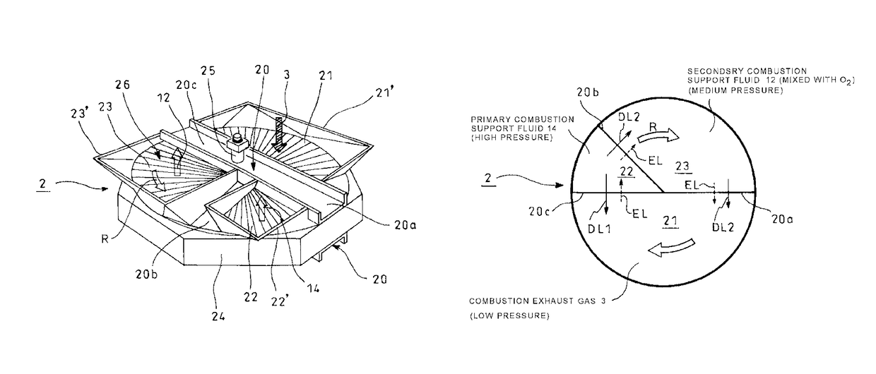
[0027]Next, an embodiment of the disclosure will be described in conjunction with the drawings.

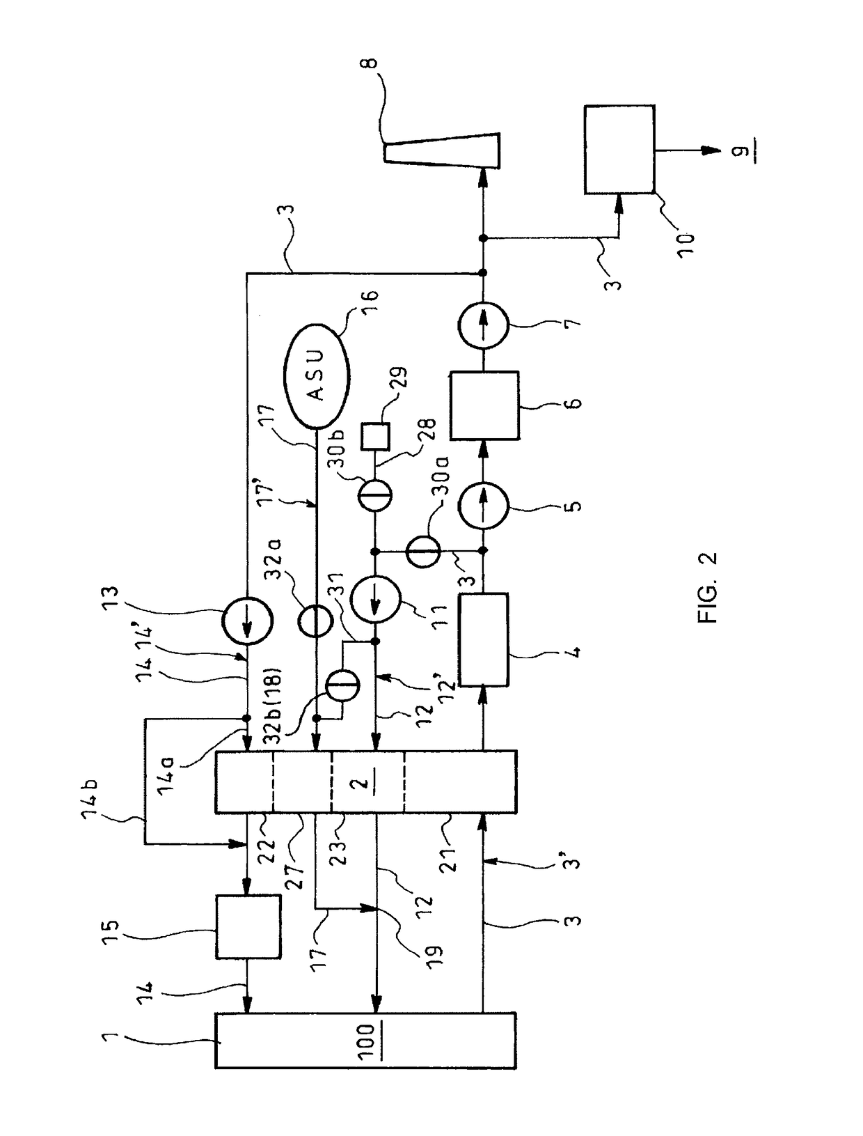
[0028]FIG. 2 schematically shows the embodiment in which a combustion-support-fluid preheating device according to the disclosure is applied to an oxyfuel combustion boiler as an oxyfuel combustion system. The oxyfuel combustion system shown in FIG. 2 comprises an oxyfuel combustion boiler 1 as an oxyfuel combustor 100 and a regenerative rotary preheater 2 providing a combustion-support-fluid preheating device.

[0029]Flue gas 3 mainly composed of carbon dioxide (CO2) and discharged from an oxyfuel combustion boiler 1 (oxyfuel combustor 100) through a flue gas duct 3′ is guided to a flue gas flow passage 21 in the regenerative rotary preheater 2, is guided to a flue gas cooler 4 for cooling and is induced by an induced draft fan 5 (IDF) into a dehydrator 6 for dehydration. Then, the flue gas 3 is boosted in pressure by a boost-up fan 7 (BUF) and guided to a stack 8. Connected to an entry sid...


PUM


Abstract

Provided are regenerative rotary preheater having flue gas flow passage through which passed is flue gas from oxyfuel combustion boiler, primary-combustion-support-fluid flow passage adjacent to the flue gas flow passage and through which passed is primary combustion support fluid with pressure higher than that of the flue gas, secondary-combustion-support-fluid flow passage adjacent to the flue gas flow passage and through which passed is secondary combustion support fluid with pressure higher than that of the flue gas and oxygen flow passage between the primary- and secondary-combustion-support-fluid flow passages and through which oxygen is passed, and an oxygen mixing section mixing the fluid preheated through the secondary-combustion-support passage with oxygen preheated through the oxygen flow passage and supplies the mixture to the oxyfuel combustion boiler.

Description

TECHNICAL FIELD[0001]The present disclosure relates to a combustion-support-fluid preheating device for an oxyfuel combustion system to preheat combustion support fluid to be supplied to an oxyfuel combustor.BACKGROUND ART[0002]Some coal-fired boilers are provided with a regenerative rotary preheater which preheats, through heat exchange with flue gas from the boiler, primary and secondary airs (primary and secondary combustion support fluids) for supply of pulverized coal to the boiler and for stable combustion of the boiler, respectively, and supplies the primary and secondary combustion support fluids to the boiler.[0003]Moreover, an oxyfuel combustion boiler has been proposed nowadays which uses not air but oxygen to burn the pulverized coal. In the oxyfuel combustion boiler, flue gas mainly composed of CO2 (carbon dioxide) is drawn from the oxyfuel combustion boiler as primary and secondary recirculation gases (primary and secondary combustion support fluids) which are guided t...

Claims


Application Information

Patent Timeline
Patent Type & Authority Patents(United States)
IPC IPC(8): F28D19/04F23L15/02F23L7/00F23C9/00
CPCF28D19/04F23C9/00F23L7/007F23L15/02Y02E20/348Y02E20/322Y02E20/344F28D19/041Y02E20/32Y02E20/34
Inventor UCHIDA, TERUTOSHI
Owner IHI CORP
Why Eureka
Try Eureka