Power detector

a technology of power detector and detector, applied in the direction of current/voltage power measurement, etc., can solve problems affecting the accuracy of power measuremen

Active Publication Date: 2018-09-25
MEDIATEK INC
View PDF24 Cites 0 Cited by
  • Summary
  • Abstract
  • Description
  • Claims
  • Application Information

AI Technical Summary

Benefits of technology

[0031]In some embodiments, power may be detected by measuring the load current and the load voltage from conductors coupled to the load. A selected phase adjustment may be introduced to correct the phase difference between the measured current and the measured voltage that may arise due to the load impedance.

Problems solved by technology

Various techniques have been proposed for measuring the power delivered to an antenna, however, they suffer from limitations that affect the accuracy of the power measurement.

Method used


Image

  • Power detector
  • Power detector
  • Power detector

Examples


Embodiment Construction

[0027]As mentioned above, various techniques have been proposed for accurately measuring load power, but they suffer from limitations that affect their accuracy.

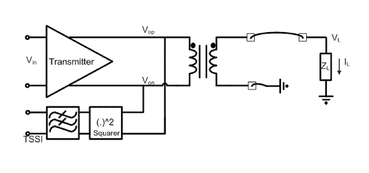
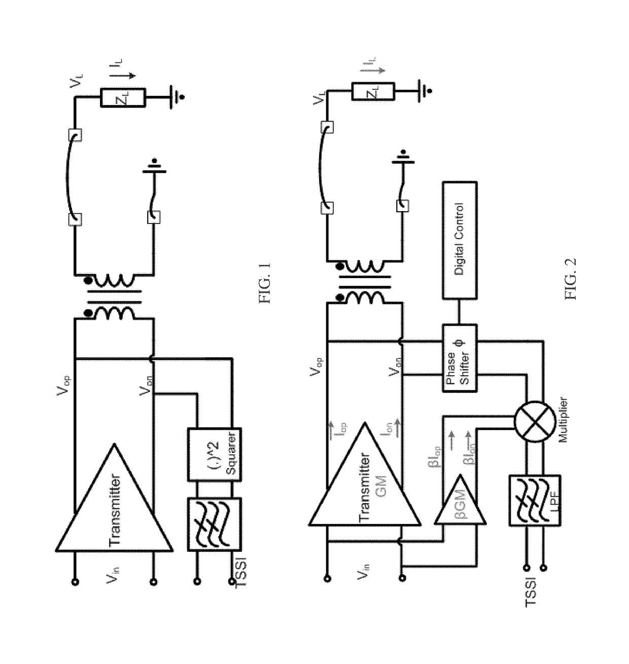
[0028]FIG. 1 shows a technique for detecting power that squares the voltage at the output of a transmitter, and calculates power based on Pout=V2out / ZL. However, a difficulty with this technique is that the load impedance ZL may vary, which may lead to an inaccurate power calculation.

[0029]FIG. 2 shows a technique that can reduce the error caused by the change in the load impedance. The voltage at the transmitter output and the current of the transmitter are measured and multiplied to obtain an indication of output power. Specifically, the current of the transmitter is measured by multiplying the transmitter input voltage with a replica of a transconductance cell. A phase shifter may account for the phase difference between the current and the voltage. However, the sensed current may not track the output current, which may l...


PUM


Abstract

Some embodiments relate to power detector including a voltage sensor configured to detect a voltage of a load and a current sensor configured to detect a current of the load. The power detector also includes circuitry configured to introduce a phase delay between the detected voltage of the load and the detected current of the load, thereby producing a voltage measurement and a current measurement. The circuitry is also configured to multiply the voltage measurement and the current measurement.

Description

CROSS-REFERENCE TO RELATED APPLICATIONS[0001]This application claims priority to U.S. provisional application Ser. No. 62 / 160,807, titled “POWER DETECTOR AND CALIBRATION METHOD,” filed May 13, 2015, which is hereby incorporated by reference in its entirety.BACKGROUND[0002]1. Technical Field[0003]The techniques described herein relate to accurately detecting power delivered to a load, such as the power delivered to an antenna by a power amplifier.[0004]2. Discussion of the Related Art[0005]In radio frequency (RF) communications, a radio signal is transmitted by driving an antenna using a power amplifier. Various techniques have been proposed for measuring the power delivered to an antenna, however, they suffer from limitations that affect the accuracy of the power measurement.SUMMARY[0006]Some embodiments relate to power detector including a voltage sensor configured to detect a voltage of a load and a current sensor configured to detect a current of the load. The power detector also...

Claims


Application Information

Patent Timeline
Patent Type & Authority Patents(United States)
IPC IPC(8): G01R21/07
CPCG01R21/07G01R21/06
Inventor CHEN, MENG-HUNGSHANA'A, OSAMA K. A.CHEE, YUENHUILU, CHIYUAN
Owner MEDIATEK INC
Why Eureka
Try Eureka