Optical time division multiplexing transmitter

a transmitter and optical time division technology, applied in the field of transmitters, can solve the problems of difficult to accurately detect and difficult to control the phase of the carrier wave very accurately, and achieve the effect of accurately detecting the phase difference of the carrier wav

Active Publication Date: 2011-06-07
OKI ELECTRIC IND CO LTD
View PDF41 Cites 0 Cited by
  • Summary
  • Abstract
  • Description
  • Claims
  • Application Information

AI Technical Summary

Benefits of technology

[0012]An object of the present invention is to provide an optical time division multiplexing transmitter which can detect the carrier wave phase difference accurately.

Problems solved by technology

Hence, the carrier wave has an extremely high frequency and, therefore, it is not easy to control the phase of the carrier wave very accurately.
The optical intensity change amount is not said to be sufficiently large and it is therefore difficult to detect the carrier wave phase difference accurately.

Method used


Image

  • Optical time division multiplexing transmitter
  • Optical time division multiplexing transmitter
  • Optical time division multiplexing transmitter

Examples


first embodiment

[0024]The optical time division multiplexing transmitter of the first embodiment of the present invention will be described first by using FIGS. 1 to 7B.

[0025]FIG. 1 is a block diagram that schematically shows the overall constitution of the optical time division multiplexing transmitter of this embodiment.

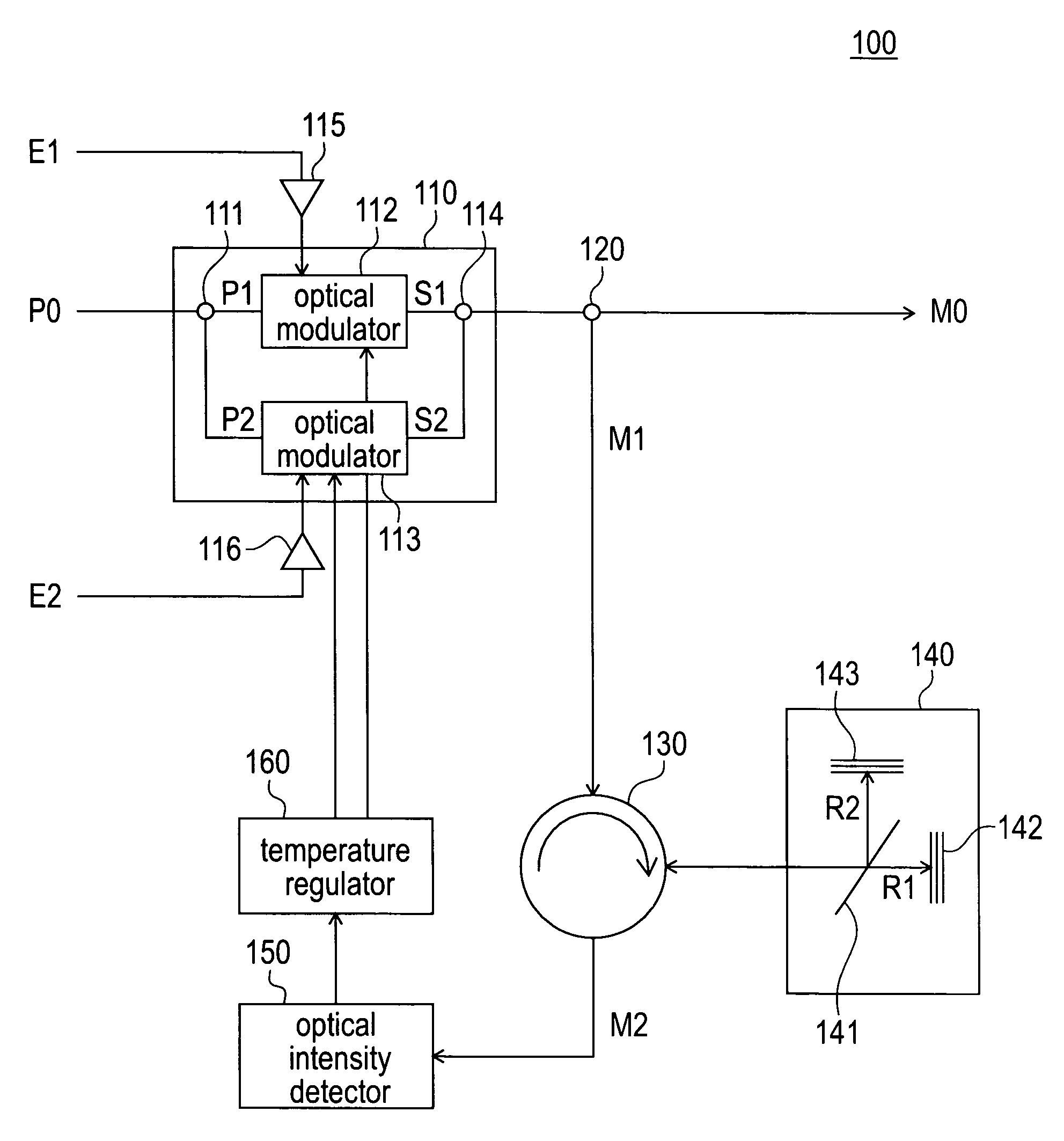
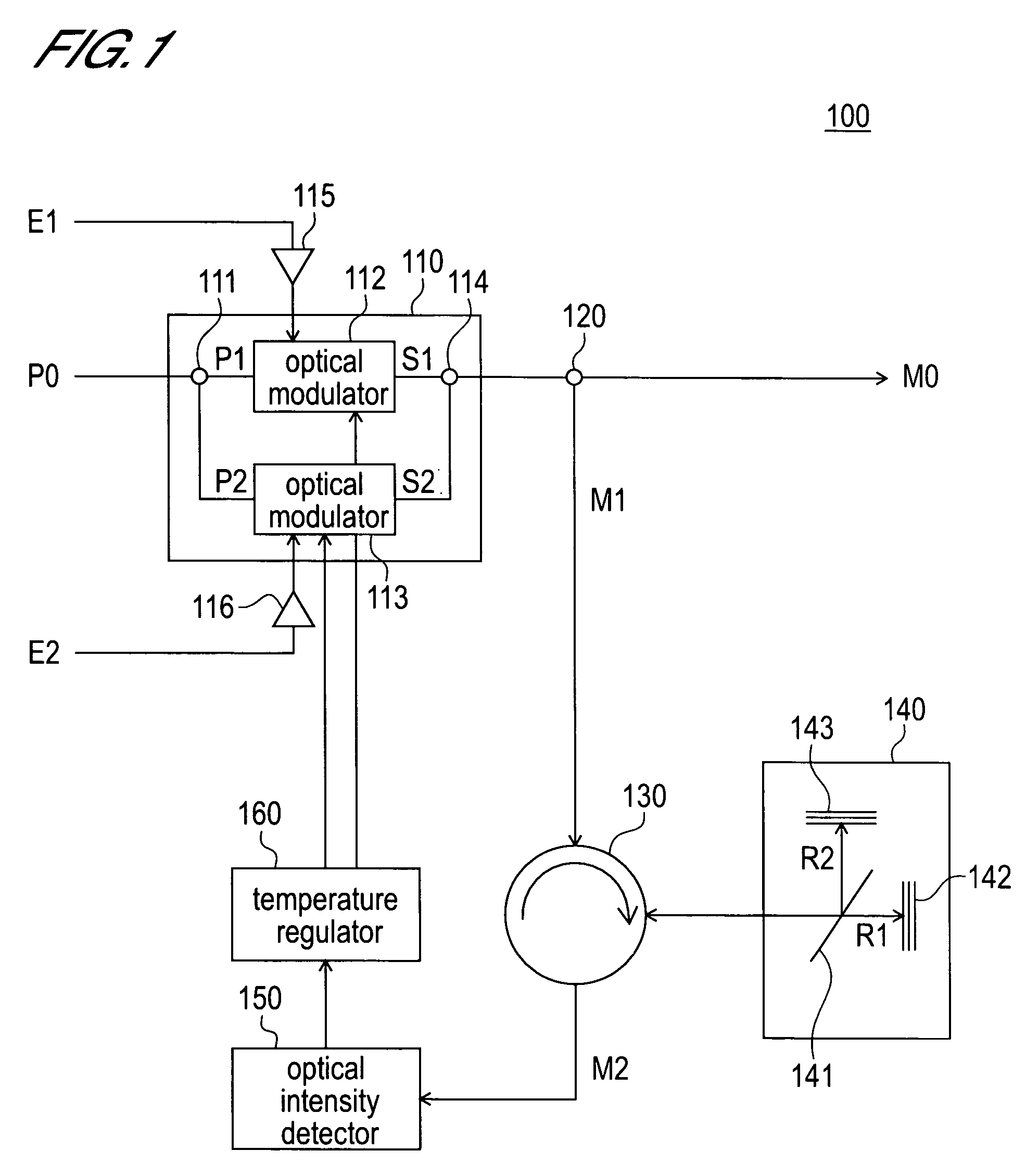
[0026]As shown in FIG. 1, the optical time division multiplexing transmitter 100 of this embodiment comprises an optical time division multiplexer 110, an optical splitter 120, a circulator 130, an optical interference device 140, an optical intensity detector 150, and a temperature regulator 160.

[0027]The optical time division multiplexer 110 generates a time-division-multiplexed optical signal by time-division-multiplexing the optical signals of two channels generated so that the phases of the carrier waves are shifted with respect to one another. The optical time division multiplexer 110 comprises an optical splitter 111, optical modulators 112 and 113, and an optical coupler 1...

second embodiment

[0049]The optical time division multiplexing transmitter of the second embodiment of the present invention will be described next by using FIG. 8.

[0050]This embodiment is an example in which an interferometer is constituted by using an FBG (Fiber Bragg Grating). The constitution of the other parts is the same as that of the first embodiment and a description of these parts is therefore omitted.

[0051]FIG. 8 is a conceptual view that conceptually shows the constitution of an interferometer 800 of this embodiment.

[0052]As shown in FIG. 8, the interferometer 800 comprises a Fiber Bragg grating 810 and a cover member 820 that covers the Fiber Bragg grating 810. Further, a first grating area 811 and a second grating area 812 are formed in the Fiber Bragg grating 810 with a phase shift area 813 interposed between the first grating area 811 and the second grating area 812.

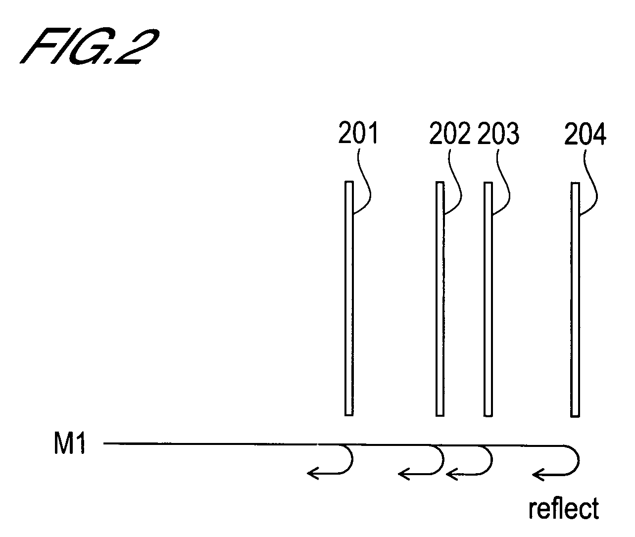
[0053]The first grating area 811 and second grating area 812 comprise a plurality of reflective faces (See FIG. 2) simil...


PUM

PropertyMeasurementUnit
temporal distancesaaaaaaaaaa

Abstract

The optical time division multiplexer generates a time-division-multiplexed optical signal by time-division-multiplexing optical signals of a plurality of channels, the carrier-wave phases of which are shifted with respect to one another. The circulator guides the multiplexed optical signals split by the optical splitter to the optical interference device and the superimposed light outputted from the optical interference device is guided to the optical intensity detector. The optical interference device extends the pulse width of the multiplexed optical signal to a width equal to or more than the bit interval and superimposes the extended light of an adjacent bit onto the extended light. The optical intensity detector detects the intensity of the superimposed light outputted by the optical interference device. The temperature regulator controls the temperature of the modulator so that the phase difference of the carrier waves constituting the optical signal trains is to be a half wavelength.

Description

BACKGROUND OF THE INVENTION[0001]1. Field of the Invention[0002]The present invention relates to a transmitter that employs an OTDM (Optical Time Division Multiplexing) system and a CS (Carrier-Suppressed)-RZ (Return to Zero) modulation system. More precisely, the present invention relates to technology for detecting and adjusting a carrier-wave phase shift in an optical time division multiplexing device that employs an optical time division multiplexing system and a CS-RZ modulation system.[0003]2. Description of Related Art[0004]Conventionally, optical time division multiplexing systems are known as signal multiplexing technology suitable for high-speed, high-capacity optical transmission systems. In addition, CS-RZ modulation systems are known as modulation technology suited to such optical transmission systems.[0005]Optical time division multiplexing systems are systems for multiplexing optical signals of a plurality of channels by switching the transmission channel at fixed tim...

Claims


Application Information

Patent Timeline
Patent Type & Authority Patents(United States)
IPC IPC(8): H04B10/04H04B10/152G02F1/01G02F1/13H04B10/06H04B10/516H04B10/07H04B10/524H04B10/61H04J14/08
CPCG02B6/29356H04J14/08H04B10/508G02B6/29398
Inventor KAGAWA, MASATOSHI
Owner OKI ELECTRIC IND CO LTD
Why Eureka
Try Eureka