Cyclic memory and disc device

a technology of cyclic memory and disc, applied in the field of cyclic memory, can solve the problems of unnecessary noise mixing into, and achieve the effects of not deteriorating, not deteriorating, and not deteriorating followability

Inactive Publication Date: 2012-10-09
PANASONIC CORP
View PDF17 Cites 0 Cited by
  • Summary
  • Abstract
  • Description
  • Claims
  • Application Information

AI Technical Summary

Benefits of technology

[0027]The cyclic memory of the present invention is constructed to correct the phase difference between the signal outputted from the memory and the compensation target signal just being detected from the optical pickup when performing high speed recording or the like in the optical disc device. Thus, the followability would not be deteriorated even when the phase difference between the signal of just-previous one period and the signal just being detected is large.
[0028]Further, the cyclic memory of the present invention is constructed to correct the phase difference between the signal outputted from the memory and the compensation target signal just being detected from the optical pickup according to the number of rotations of the disc. Thus, the followability would not be deteriorated even when the number of rotations of the disc varies.
[0029]Further, the cyclic memory of the present invention is constructed to correct the phase difference between the signal outputted from the memory and the compensation target signal just being detected from the optical pickup according to the position of the optical pickup. Thus, the followability would not be deteriorated irrespective of at which position in the radial direction of the disc the optical pickup is located.
[0030]Further, the disc device of the present invention is provided with the cyclic memory for correcting the phase difference between the signal of just-previous one period and the signal just being detected, in the control system which controls the actuator or the motor for locating the light / magnetism generating head at a predetermined position on the disc. Thus, the followability in the focus / tracking control during high-speed recording / reproduction can be enhanced, thereby significantly reducing the residual deviation.

Problems solved by technology

When performing such repetitive control, however, since the signal of just-previous one period is stored in the memory, if a non-periodic signal caused by flaws on the disc or disturbance such as vibration applied to the device is undesirably given as an input signal, unnecessary noise might be mixed into the control system by learning this signal.

Method used


Image

  • Cyclic memory and disc device
  • Cyclic memory and disc device
  • Cyclic memory and disc device

Examples


embodiment 1

(Embodiment 1)

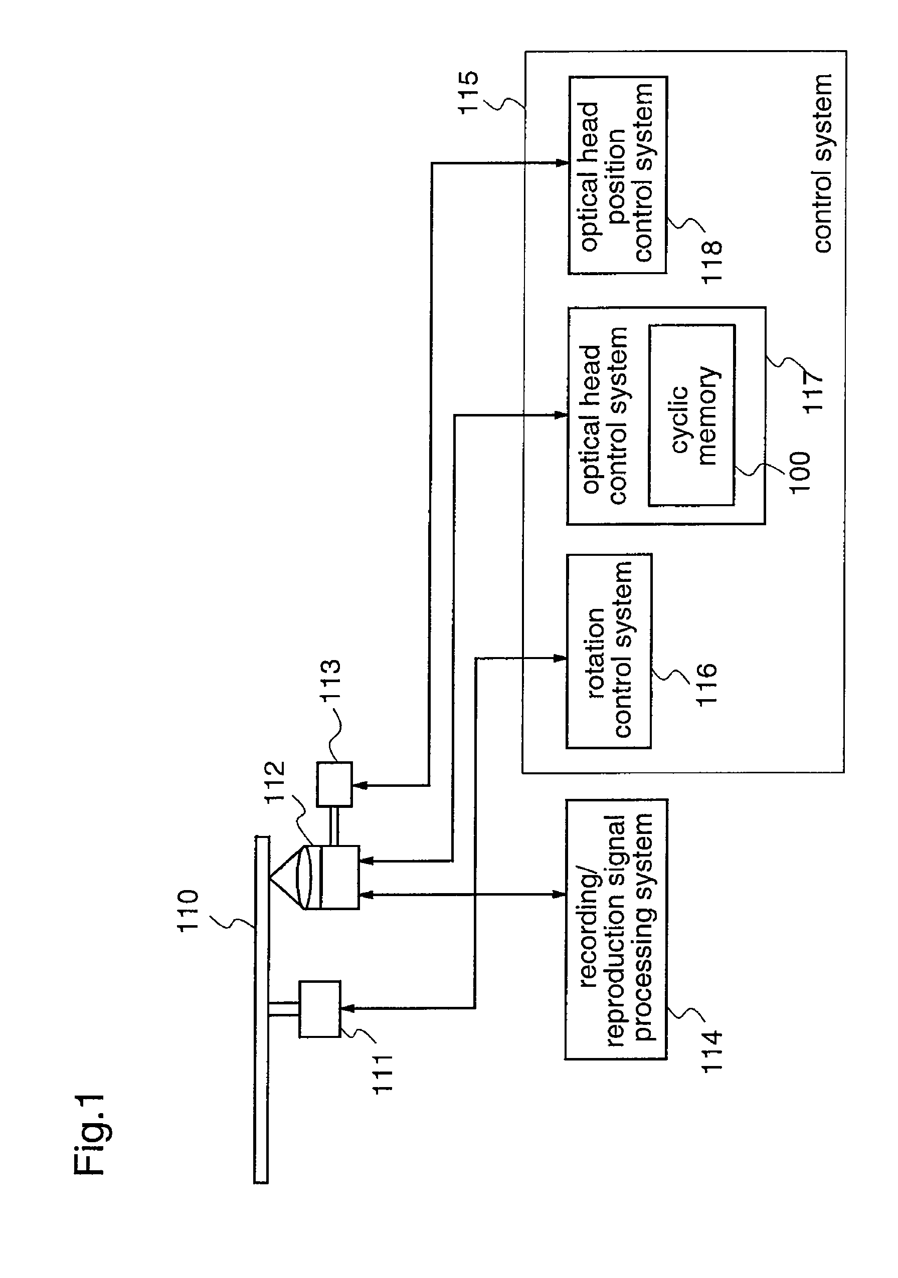
[0074]FIG. 1 is a diagram illustrating the construction of an optical disc device having a cyclic memory 100 according to a first embodiment of the present invention.

[0075]With reference to FIG. 1, the optical disc device comprises a recording / reproduction signal processing system 114 for processing recording data to be recorded on an optical disc 110 or reproduction data read from the optical disc 110, and a control system 115 for driving the optical disc device. The control system 115 comprises a rotation control system 116 for controlling a spindle motor 111 which rotates the optical disc 110, an optical head control system 117 for controlling an actuator or motor (not shown) which speedily and precisely drives an optical head 112 in two axial directions, i.e., a light axis direction and a direction perpendicular to the light axis, to focus a light spot emitted from the optical head 112 onto a recording film or a target track on the optical disc 110, and an optical ...

embodiment 2

(Embodiment 2)

[0096]A cyclic memory relating to a second embodiment of the present invention is constituted to perform, even when the rpm of the disc varies in the cyclic memory of the first embodiment, phase correction according to the rpm to realize appropriate repetitive control.

[0097]FIG. 4 is a diagram illustrating the construction of the cyclic memory 100a of the second embodiment.

[0098]In FIG. 4, reference numeral 25 denotes an rpm detection unit which detects the rpm of the motor according to motor rotation number information of the spindle motor that rotates the optical disc 110, and controls the phase correction unit 19 on the basis of the detection result.

[0099]Further, in this second embodiment, the phase correction unit 19 sets a phase correction amount according to the rpm of the motor. For example, when the optical disc device performs recording / reproduction at a high speed, the signal of just-previous one period stored in the memory 15 is shorter in period relative t...

embodiment 3

(Embodiment 3)

[0112]A cyclic memory according to a third embodiment of the present invention is constituted to perform, even when the position of the optical pickup in the radial direction of the optical disc varies in the cyclic memory of the first embodiment, phase correction according to the position information of the optical pickup to realize appropriate repetitive control.

[0113]FIG. 5 is a diagram illustrating the construction of the cyclic memory 100b according to the third embodiment.

[0114]In FIG. 5, reference numeral 26 denotes a position detection unit for detecting the position of the optical pickup in the radial direction of the optical disc, and controlling the phase correction unit 19 on the basis of the detection result.

[0115]In this third embodiment, the phase correction unit 19 sets a phase correction amount according to the position of the optical pickup in the radial direction of the disc, which is detected by the position detection unit 26. For example, when the ...


PUM

PropertyMeasurementUnit
periodic frequencyaaaaaaaaaa
frequencyaaaaaaaaaa
phaseaaaaaaaaaa

Abstract

Provided is an orbiting memory capable of suppressing residual deviation even when a phase difference is caused between a signal to be compensated and information stored in a memory to be fed back and a disc device using the orbiting memory. The disc device includes: an adder to which a signal (s10) to be compensated and having a cyclic frequency component such as a control system error signal is inputted; and a feed back signal system for successively updating and storing an output signal of the adder for each cycle in a memory and inputting one-cycle information stored in the memory to the adder. The feed back signal system includes: a filter unit for outputting a signal contained in a learning band which is arbitrarily set among output signals from the adder; the memory for successively updating and storing the output signal of the filter unit; a phase correction unit capable of arbitrarily setting a phase amount when inputting the output of the memory to the adder; and a gain element for multiplying the one-cycle information subjected to the phase correction by the phase correction unit by a value not smaller than 0 and not greater than 1 and inputting the obtained value to the adder.

Description

RELATED APPLICATIONS[0001]This application is the U.S. National Phase under 35 U.S.C. §371 of International Application No. PCT / JP2007 / 052680, filed on Feb. 15, 2007, which in turn claims the benefit of Japanese Application No. 2006-037440, filed on Feb. 15, 2006, the disclosures of which Applications are incorporated by reference herein.TECHNICAL FIELD[0002]The present invention relates to a cyclic memory used for controlling a control system, and a disc device including the cyclic memory.BACKGROUND ART[0003]In recent years, with progress in speed-up and high-densification for an optical disc, accuracy improvement in optical servo for maintaining a focal point of a laser beam on an information recording track of the disc in an optical disc device has been rapidly demanded. As a means for improving the accuracy of optical servo, repetitive control (learning control) has attracted attention. The repetitive control controls, with a one-period previous deviation signal being stored in ...

Claims


Application Information

Patent Timeline
Patent Type & Authority Patents(United States)
IPC IPC(8): G11B20/20G11B27/10
CPCG11B20/10009G11B20/10027G11B20/10046G11B20/10222G11B7/095G11B2220/2537
Inventor KATAYAMA, TSUYOSHI
Owner PANASONIC CORP
Why Eureka
Try Eureka