
Munition fuze with blast initiated inductance generator for power supply and laser ignitor

a technology of inductance generator and munition fuze, which is applied in the field of fuzes, can solve the problems of systemic problems of traditional pyrotechnic fuzes, adverse effects of presence of such compounds on the environment, and potential impact on compliance with environmental standards

Active Publication Date: 2018-10-02
UNITED STATES OF AMERICA THE AS REPRESENTED BY THE SEC OF THE ARMY
View PDF16 Cites 5 Cited by
  • Summary
  • Abstract
  • Description
  • Claims
  • Application Information

AI Technical Summary

Benefits of technology

This patent describes a fuze for a munition and a fuze for a hand grenade. The fuze includes an inductance generator assembly, a laser igniter assembly, a delay circuit, and a striker assembly. The inductance generator assembly generates electric power from a detonation of a primer charge and provides the electric power to the laser igniter. The straker assembly detonates the primer charge. The delay circuit controls the timing of ignition by the laser igniter assembly. The invention enables precise detonation of the munition or hand grenade at a desired time.

Problems solved by technology

However, these successive energetic compounds often include hazardous chemical compounds such as perchlorates and heavy metals.
The presence of such compounds can have adverse effects on the environment and potentially impact compliance with environmental standards.
Additionally, traditional pyrotechnic fuzes have systemic issues in the field related to insensitive munition compliance requirements.
These issues create potential hazards for users in both logistical and tactical configurations.
Past efforts to integrate electronic fuzes in grenades have been hampered by inadequate power supplies.

Method used


Image

  • Munition fuze with blast initiated inductance generator for power supply and laser ignitor
  • Munition fuze with blast initiated inductance generator for power supply and laser ignitor
  • Munition fuze with blast initiated inductance generator for power supply and laser ignitor

Examples


Embodiment Construction

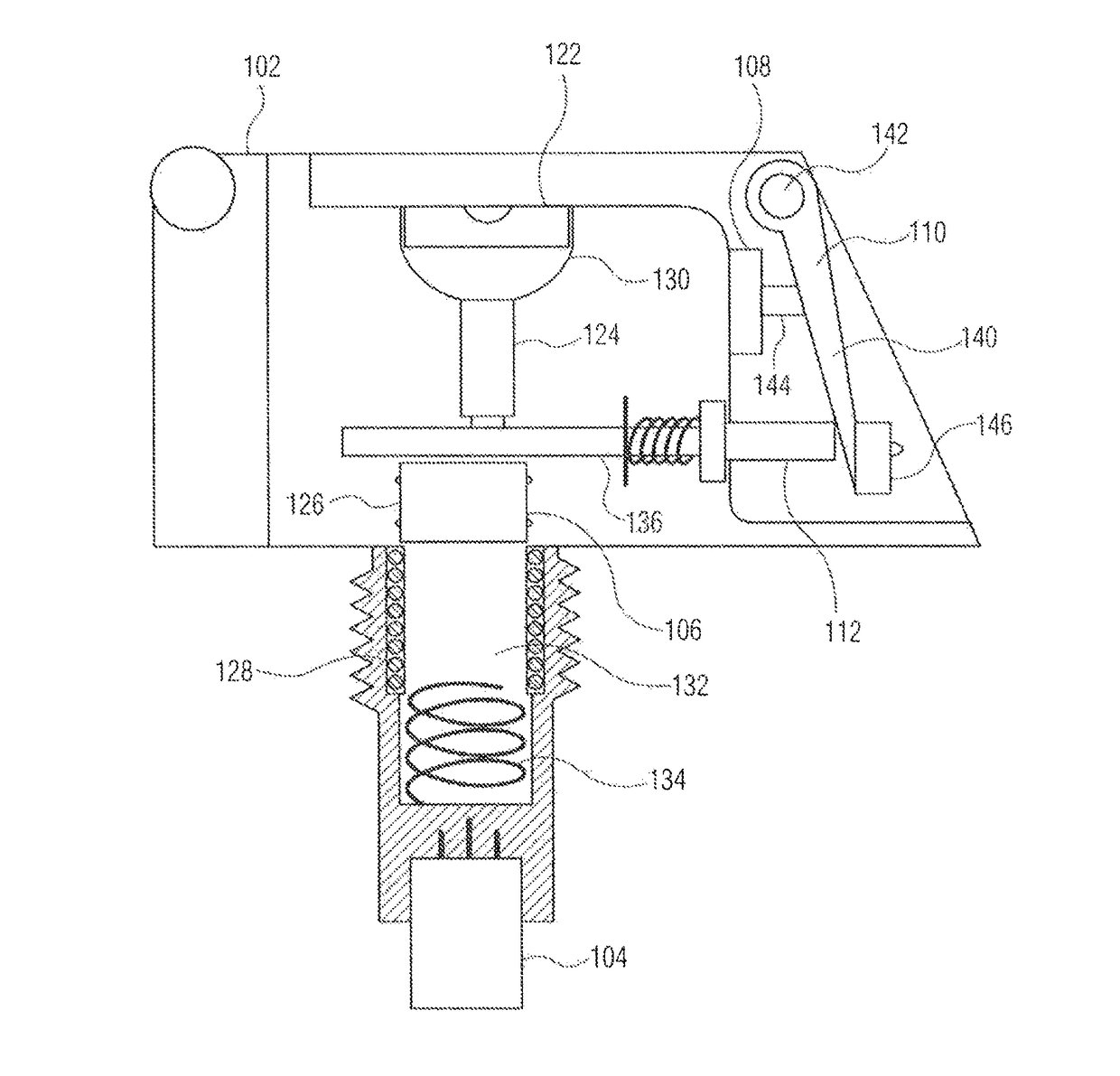
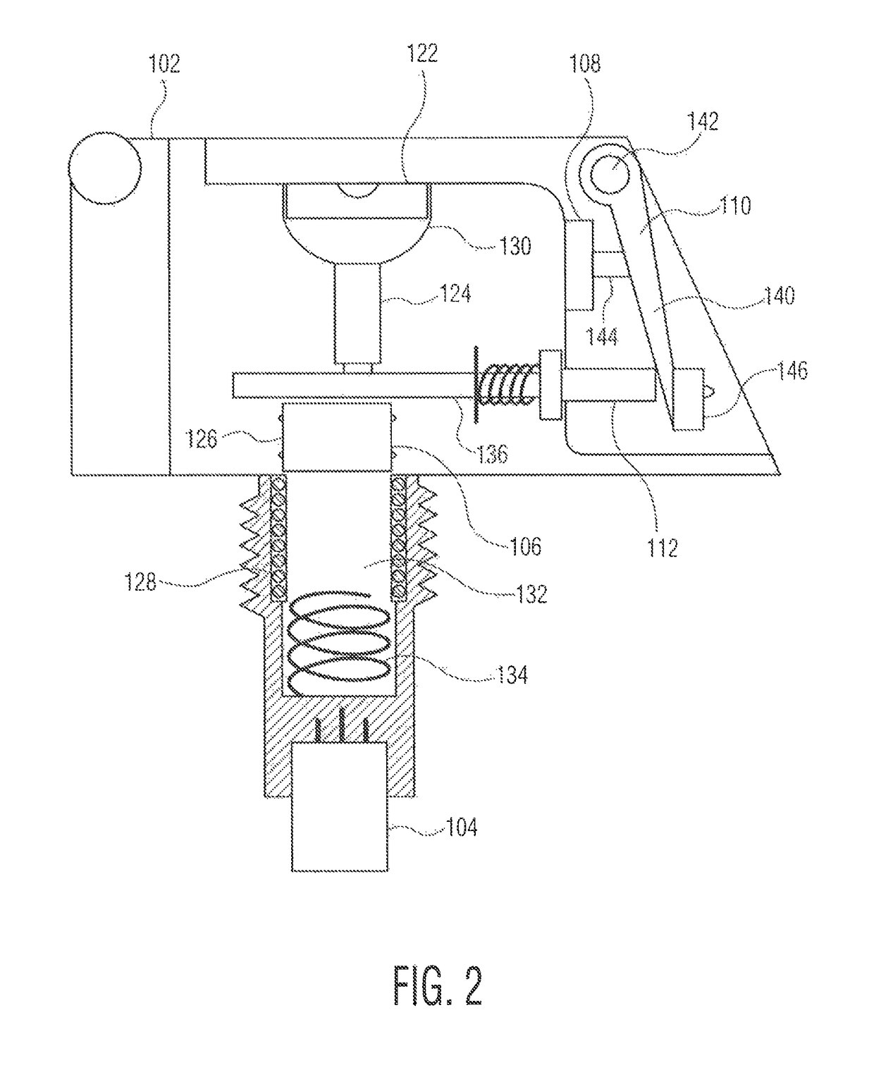
[0022]The munition employs an energetically initiated electromagnetic pulse through a coil which induces a voltage intended to be used for the operation of an electronic time delay circuit and subsequent ignition of a detonation device. Explosive energy from a primer is employed to activate a piston actuator and move a generator core through a generator coil to induce the voltage. The voltage is supplied to an electronic time delay circuit. After a set time, the delay circuit supplies power to a light emitting diode (LED) laser igniter which detonates the munition. A striker assembly, in addition to initiating the primer, functions as an electric safety. Furthermore, the striker assembly constrains a physical out of line safety feature until the munition is intentionally activated.

[0023]Advantageously, the blast initiated inductance generator allows for the elimination of significant amounts of hazardous pyrotechnic materials including perchlorates and heavy metals thereby greatly f...


PUM


Abstract

The munition employs an energetically initiated electromagnetic pulse through a coil which induces a voltage intended to be used for the operation of an electronic time delay circuit and subsequent ignition of a detonation device. Explosive energy from a primer is employed to move a generator core through a generator coil to induce the voltage. The voltage is supplied to a delay circuit. After a set time, the delay circuit supplies power to a laser igniter which detonates the munition. A striker assembly, in addition to initiating the primer, functions as an out of line safety as well as an electric safety.

Description

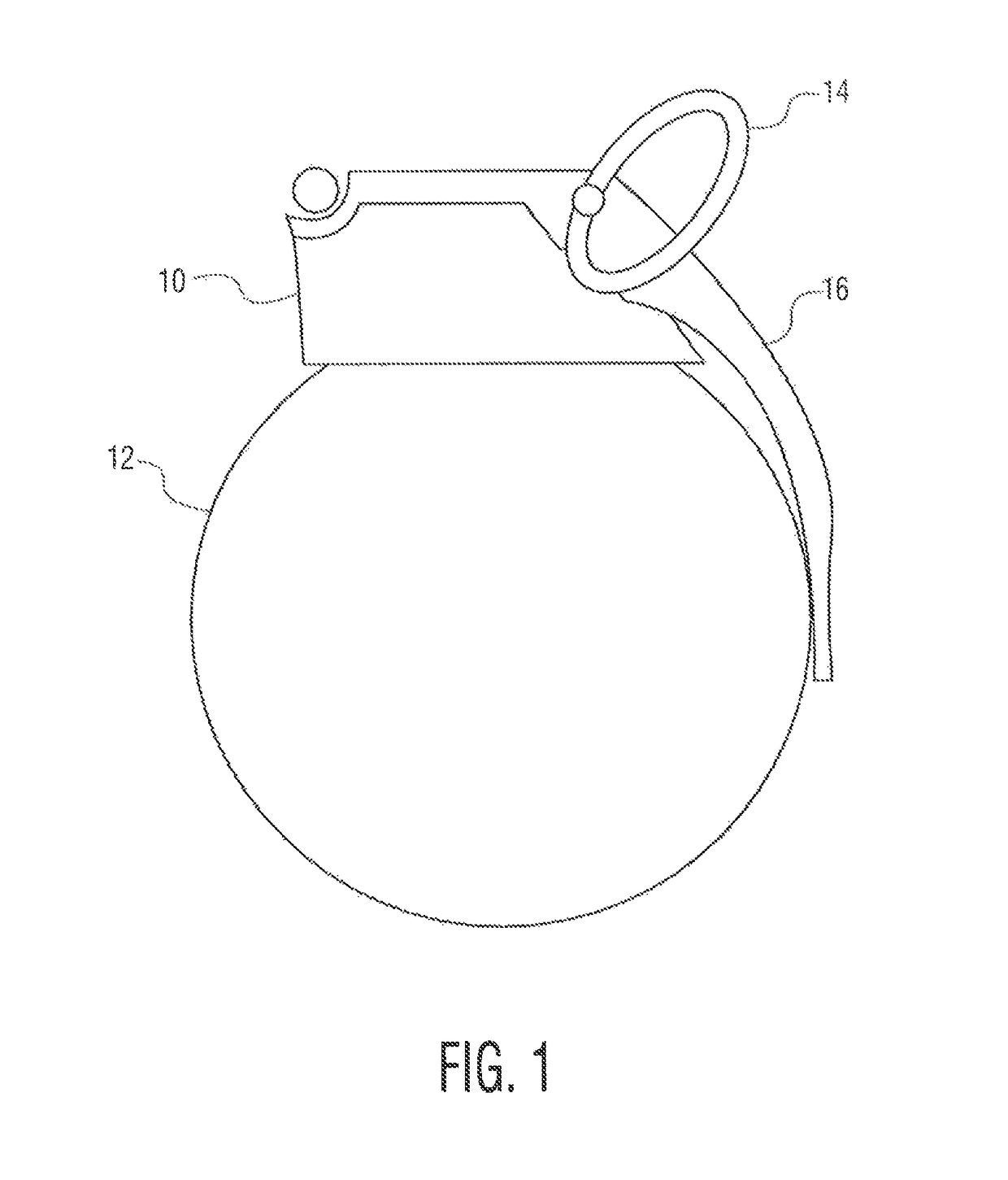
CROSS-REFERENCE TO RELATED APPLICATIONS[0001]This application claims the benefit under 35 USC § 119(e) of U.S. provisional patent application 62 / 404,893 filed on Oct. 6, 2016.STATEMENT OF GOVERNMENT INTEREST[0002]The inventions described herein may be manufactured, used and licensed by or for the United States Government.BACKGROUND OF THE INVENTION[0003]The invention relates in general to fuzes and in particular to fuzes for munitions, such as hand grenades.[0004]Conventional hand grenades typically include pyrotechnic based fuzes. In such a fuze, a firing pin strikes a primer to initiate the energetic chain. The primer ignites a delay mixture which after a set period of time ignites one or more successive energetic compounds to produce the explosive effect of the grenade.[0005]However, these successive energetic compounds often include hazardous chemical compounds such as perchlorates and heavy metals. The presence of such compounds can have adverse effects on the environment and p...

Claims


Application Information

Patent Timeline
Patent Type & Authority Patents(United States)
IPC IPC(8): F42C11/04F42C11/06
CPCF42C11/06F42C11/04F42C14/025
Inventor CASKA, KEVINZIMMER, ANDREW
Owner UNITED STATES OF AMERICA THE AS REPRESENTED BY THE SEC OF THE ARMY
Learn More