Method and apparatus for forming interface between coaxial cable and connector

a technology of coaxial cable and connector, which is applied in the direction of solventing apparatus, manufacturing tools, heating appliances, etc., can solve the problems of compromising the electrical performance of the connector interface, and achieve the effect of reducing the formation of bubbles

Active Publication Date: 2018-10-02
COMMSCOPE TECH LLC
View PDF7 Cites 0 Cited by
  • Summary
  • Abstract
  • Description
  • Claims
  • Application Information

AI Technical Summary

Benefits of technology

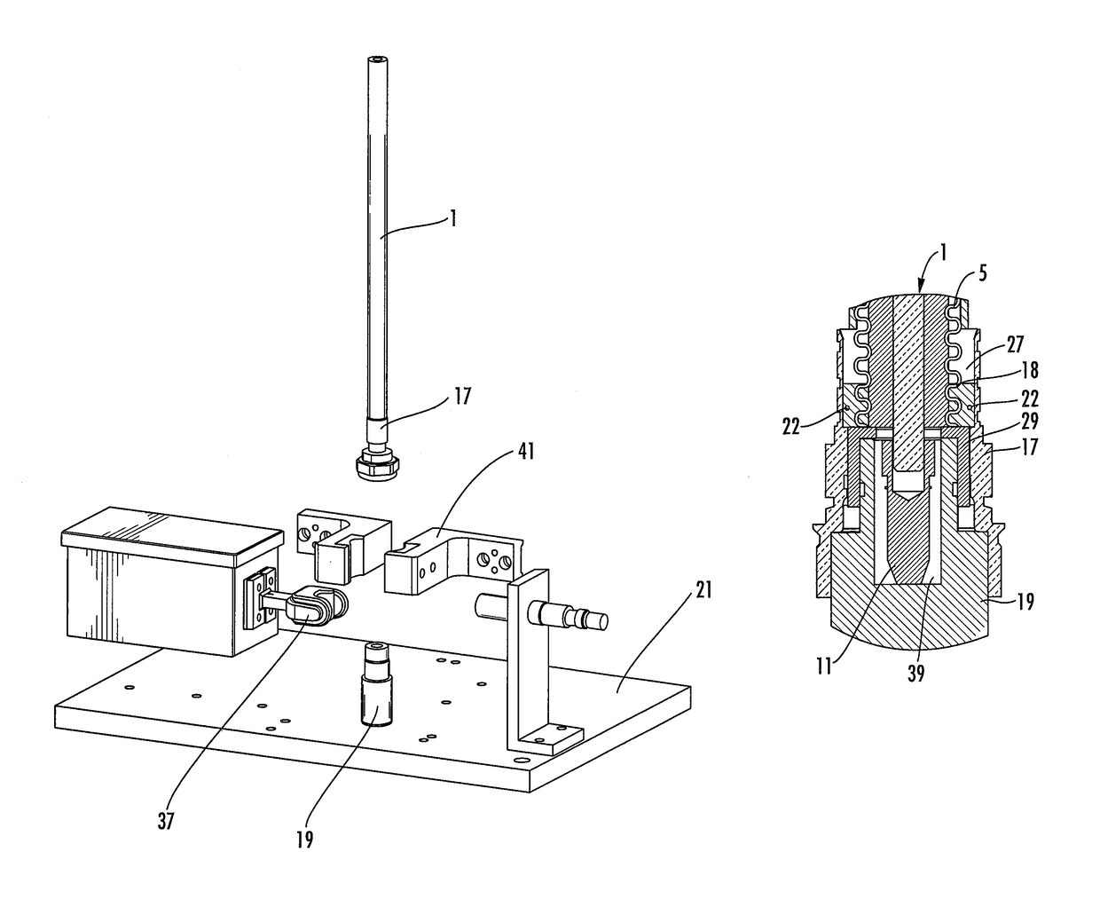
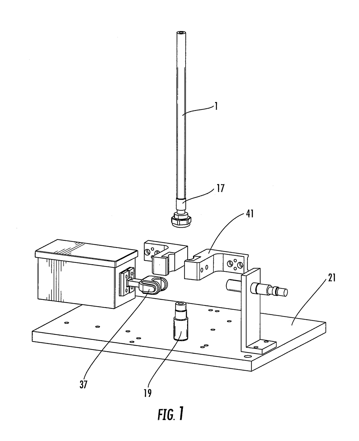
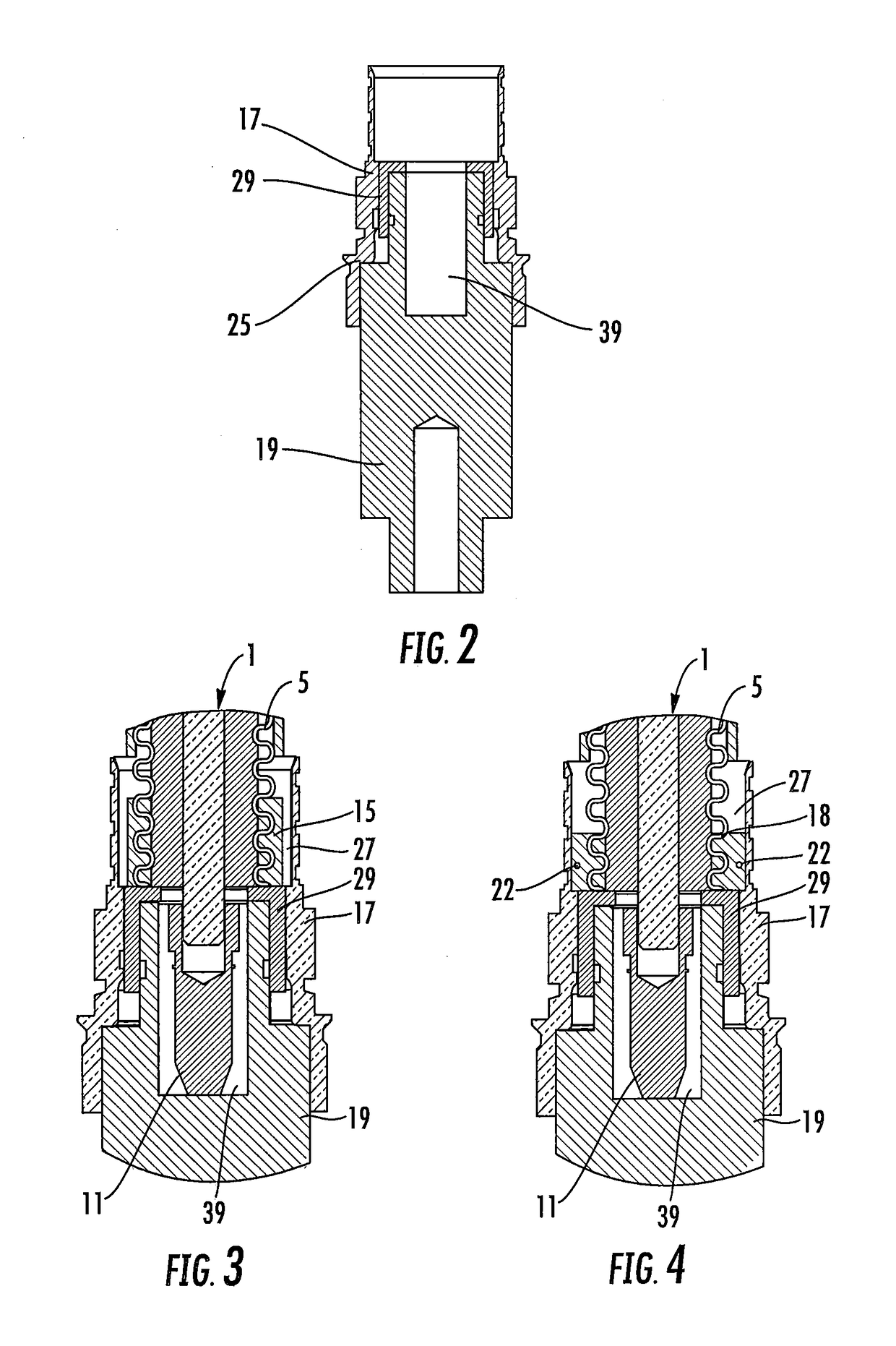
[0007]As a first aspect, embodiments of the invention are directed to a method of forming a solder joint between a coaxial cable and a coaxial connector. The method comprises the steps of: positioning a solder element between an end of an outer conductor of the coaxial cable and a connector body of the connector, wherein the solder element is positioned within a vacuum chamber; melting the solder element to form a solder joint between the outer conductor and the connector body, the solder joint including a lower surface formed by contact with a mounting structure; and applying suction to the melting solder element to reduce the formation of bubbles within the solder joint.
[0008]As a second aspect, embodiments of the invention are directed to a method for attaching a connector to a coaxial cable, comprising the steps of: positioning a solder element between an end of an outer conductor of the coaxial cable and a connector body of the connector; positioning the connector body on a mounting structure; melting the solder element to form a solder joint between the outer conductor and the connector body, the solder joint including a surface formed by contact with the mounting structure, the melting step being performed as the solder element resides in a vacuum chamber; and applying suction to the melting solder element to reduce the formation of bubbles within the solder joint.

Problems solved by technology

One issue that can arise with this technique is the formation of air bubbles within the solder; if such bubbles form in locations along the signal path, the electrical performance of the connector interface can be compromised.

Method used


Image

  • Method and apparatus for forming interface between coaxial cable and connector
  • Method and apparatus for forming interface between coaxial cable and connector
  • Method and apparatus for forming interface between coaxial cable and connector

Examples


Embodiment Construction

[0017]The present invention is described with reference to the accompanying drawings, in which certain embodiments of the invention are shown. This invention may, however, be embodied in many different forms and should not be construed as limited to the embodiments that are pictured and described herein; rather, these embodiments are provided so that this disclosure will be thorough and complete, and will fully convey the scope of the invention to those skilled in the art. It will also be appreciated that the embodiments disclosed herein can be combined in any way and / or combination to provide many additional embodiments.

[0018]Unless otherwise defined, all technical and scientific terms that are used in this disclosure have the same meaning as commonly understood by one of ordinary skill in the art to which this invention belongs. The terminology used in the above description is for the purpose of describing particular embodiments only and is not intended to be limiting of the inven...


PUM

PropertyMeasurementUnit
heataaaaaaaaaa
vacuumaaaaaaaaaa
electrical performanceaaaaaaaaaa

Abstract

A method of forming a solder joint between a coaxial cable and a coaxial connector includes the steps of: positioning a solder element between an end of an outer conductor of the coaxial cable and a connector body of the connector, wherein the solder element is positioned within a vacuum chamber; melting the solder element to form a solder joint between the outer conductor and the connector body, the solder joint including a lower surface formed by contact with a mounting structure; and applying suction to the melting solder element to reduce the formation of bubbles within the solder joint.

Description

RELATED APPLICATION[0001]The present application claims priority from and the benefit of U.S. Provisional Patent Application No. 62 / 131,105, filed Mar. 10, 2015, the disclosure of which is hereby incorporated herein in its entirety.FIELD OF THE INVENTION[0002]invention relates generally to a connector and cable interconnection, and more specifically to a connector and cable interconnection method and apparatus with improved manufacturing efficiency and electrical performance characteristics.BACKGROUND OF THE INVENTION[0003]Coaxial connectors are commonly utilized in RF communications systems. A typical coaxial cable includes an inner conductor, an outer conductor, a dielectric layer that separates the inner and outer conductors, and a jacket that covers the outer conductor. Coaxial cable connectors may be applied to terminate coaxial cables, for example, in communication systems requiring a high level of precision and reliability.[0004]Coaxial connector interfaces provide a connect / ...

Claims


Application Information

Patent Timeline
Patent Type & Authority Patents(United States)
IPC IPC(8): H01R43/02B23K3/08H01R9/05B23K3/047
CPCH01R43/0263B23K3/087B23K3/0475Y10T29/53213H01R43/0235Y10T29/49169Y10T29/49179H01R9/05
Inventor HARWATH, FRANK A.PAYNTER, JEFFREY D.FLEMING, JAMES P.SMENTEK, DAVID J.
Owner COMMSCOPE TECH LLC
Why Eureka
Try Eureka